Measuring device and measuring method for measuring the power of a high-frequency signal

Active Publication Date: 2009-07-30
ROHDE & SCHWARZ GMBH & CO KG
View PDF8 Cites 6 Cited by
  • Summary
  • Abstract
  • Description
  • Claims
  • Application Information

AI Technical Summary

Benefits of technology

[0007]The invention is based upon the object of providing a measuring device and a measuring method for measuring the power

Problems solved by technology

The disadvantage of the measuring device known from DE 199 55 342 A1 is the use of parallel measurement branches, as a result of which the measuring device suffers from an extremely complex design.
In practi

Method used


Image

  • Measuring device and measuring method for measuring the power of a high-frequency signal
  • Measuring device and measuring method for measuring the power of a high-frequency signal
  • Measuring device and measuring method for measuring the power of a high-frequency signal

Examples


Example

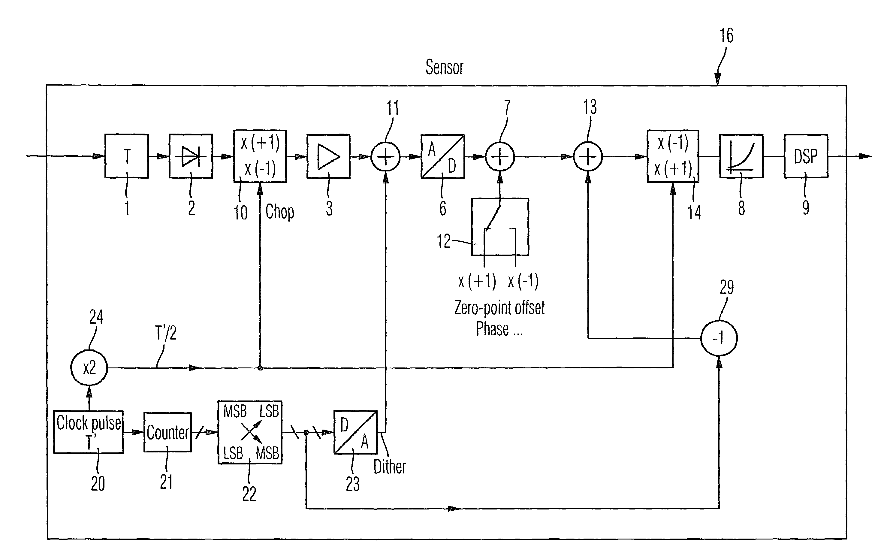
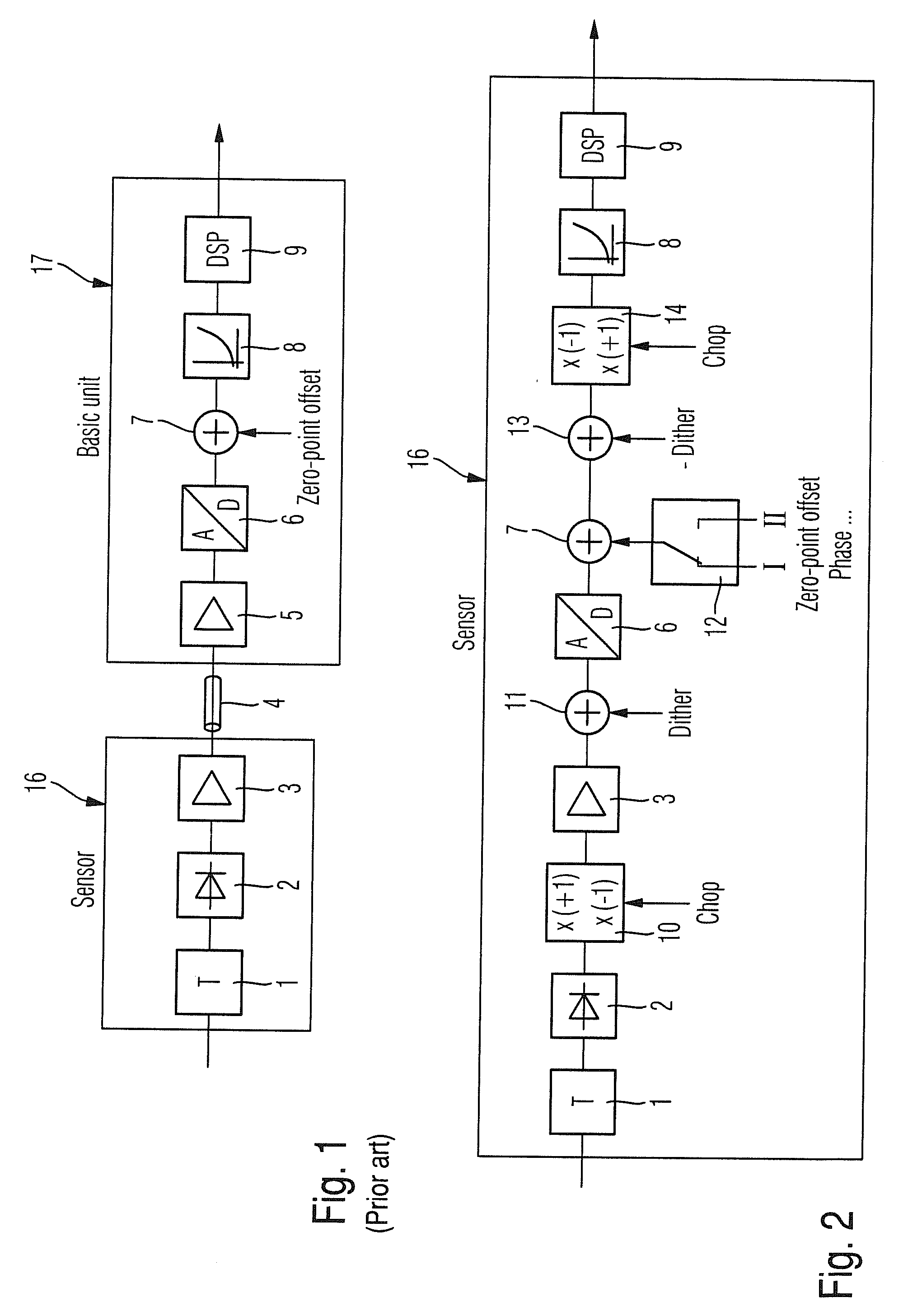
[0020]FIG. 1 shows a hitherto usual configuration of a measuring device for measuring the envelope-power and the average-power value. An attenuation element 1, an envelope detector 2, which can be designed as a diode detector, and a pre-amplifier or respectively line driver 3 are arranged in a sensor 16. The sensor 16 is connected via a connecting cable 4 to the basic unit 17. The main amplifier 5, an analog / digital converter 6, a summation stage 7 for subtraction of the zero-point offset, a device 8 for curve correction and a digital signal processor with further evaluation functions, for example, for displaying the envelope curves, for calculation of the average-power value and so on, are disposed in the basic unit 17. The device for curve correction 8 and the digital signal processor 9 together form an evaluation device 8, 9.

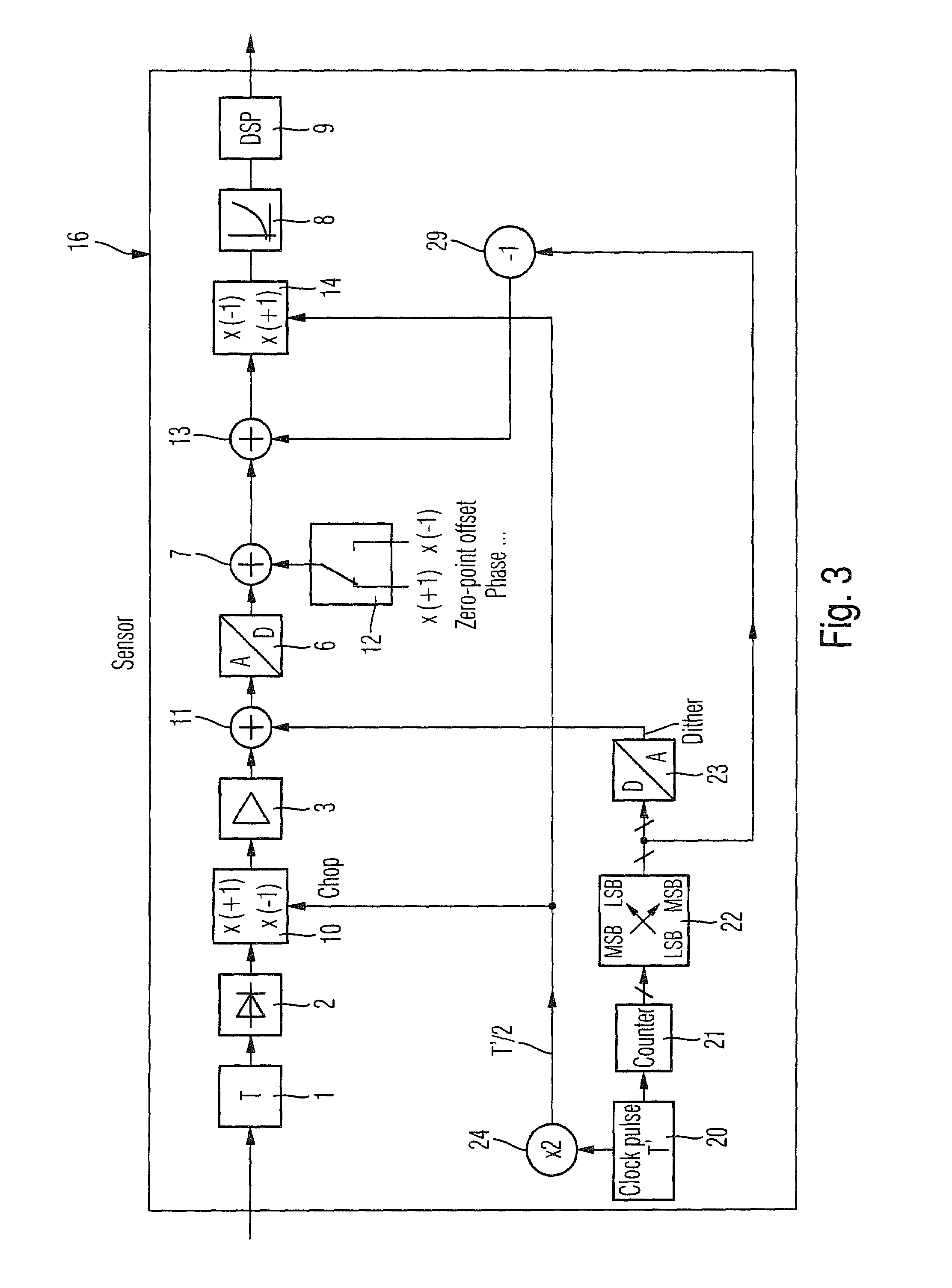
[0021]FIG. 2 shows an exemplary embodiment of the measuring device according to the invention in an operating mode A, which is used for measuring the envelop...


PUM


Abstract

A measuring device for measuring the power of a high-frequency signal including a detector for detecting the high-frequency signal and for generating an analog detector signal, an analog/digital converter for generating a digital signal and an evaluation device for evaluating the digital signal. A dither supply device for the supply of a dither signal and a chopper, which periodically chops the analog detector signal with a chopper signal, are disposed between the detector and the analog/digital converter. In this context, the dither signal is supplied synchronously to the chopper signal.

Description

CROSS-REFERENCE TO RELATED APPLICATION[0001]The present application claims priority to PCT Application No. PCT / EP2007 / 003704, filed on Apr. 26, 2007, German Patent Application No. 10 2006 038 030.4, filed on Aug. 14, 2006, German Patent Application No. 10 2006 046 966.6, filed on Oct. 4, 2006, and German Patent Application No. 10 2006 024 698.5, filed on May 26, 2006, the entire contents of which are herein incorporated by reference.BACKGROUND OF THE INVENTION[0002]1. Field of the Invention[0003]The invention relates to a measuring device for measuring the power, in particular, the envelope power of a high-frequency signal.[0004]2. Discussion of the Background[0005]A measuring device is known from DE 199 55 342 A1. With the measuring device disclosed in this specification, it is possible to measure both the envelope power and also the mean-power or RMS (root mean square) value. To cover the maximum possible dynamic range, the measurement range is divided into several subdivisions, w...

Claims


Application Information

Patent Timeline
IPC IPC(8): G01R21/00
CPCG01R21/01G01R19/2506
Inventor BRATFISCH, TORALFBENISCH, CHRISTIAN
Owner ROHDE & SCHWARZ GMBH & CO KG
Why Eureka
Try Eureka