Pulsed spray system of reduced power consumption

a technology of power consumption and spray system, applied in the field of mobile equipment, to achieve the effect of wear of the pump, reducing the average power consumption, and more benefits

Inactive Publication Date: 2009-08-06
SMITH CLYDE MERIWETHER
View PDF0 Cites 33 Cited by
  • Summary
  • Abstract
  • Description
  • Claims
  • Application Information

AI Technical Summary

Benefits of technology

[0003]In one aspect of the invention, a hydraulic circuit is disclosed that includes at least fluid source, a fluid destination, a fluid pressurizing means and a fluid flow interrupter means. Typically, this circuit will have an atmospheric pressure fluid reservoir, a spray nozzle, a electric motor driven pump and a ON / OFF, electrically operated modulating valve. Because the present invention has a purpose of reducing the average power consumption and wear on pump and motor, the invention anticipates that more benefit accrues in applications where spray from the nozzle is more off than on. The circuit arrangement and components are comprised to achieve a low pressure differential across the pump when there is no demand for spray. It is the low pressure differential that is related to the lowered average power consumption and wear. A lower average power consumption may be important because of generator or alternator limitations on mobile equipment. Whereas peak power consumption may not be a limitation because of the high instantaneous power capability of a battery.

Problems solved by technology

It is the low pressure differential that is related to the lowered average power consumption and wear.

Method used


Image

  • Pulsed spray system of reduced power consumption
  • Pulsed spray system of reduced power consumption
  • Pulsed spray system of reduced power consumption

Examples


Embodiment Construction

[0012]Reference will now be made in detail to exemplary embodiments of the invention, an example of which is illustrated in the accompanying drawings. Wherever possible, the same reference numbers will be used throughout the drawings to refer to the same or like parts.

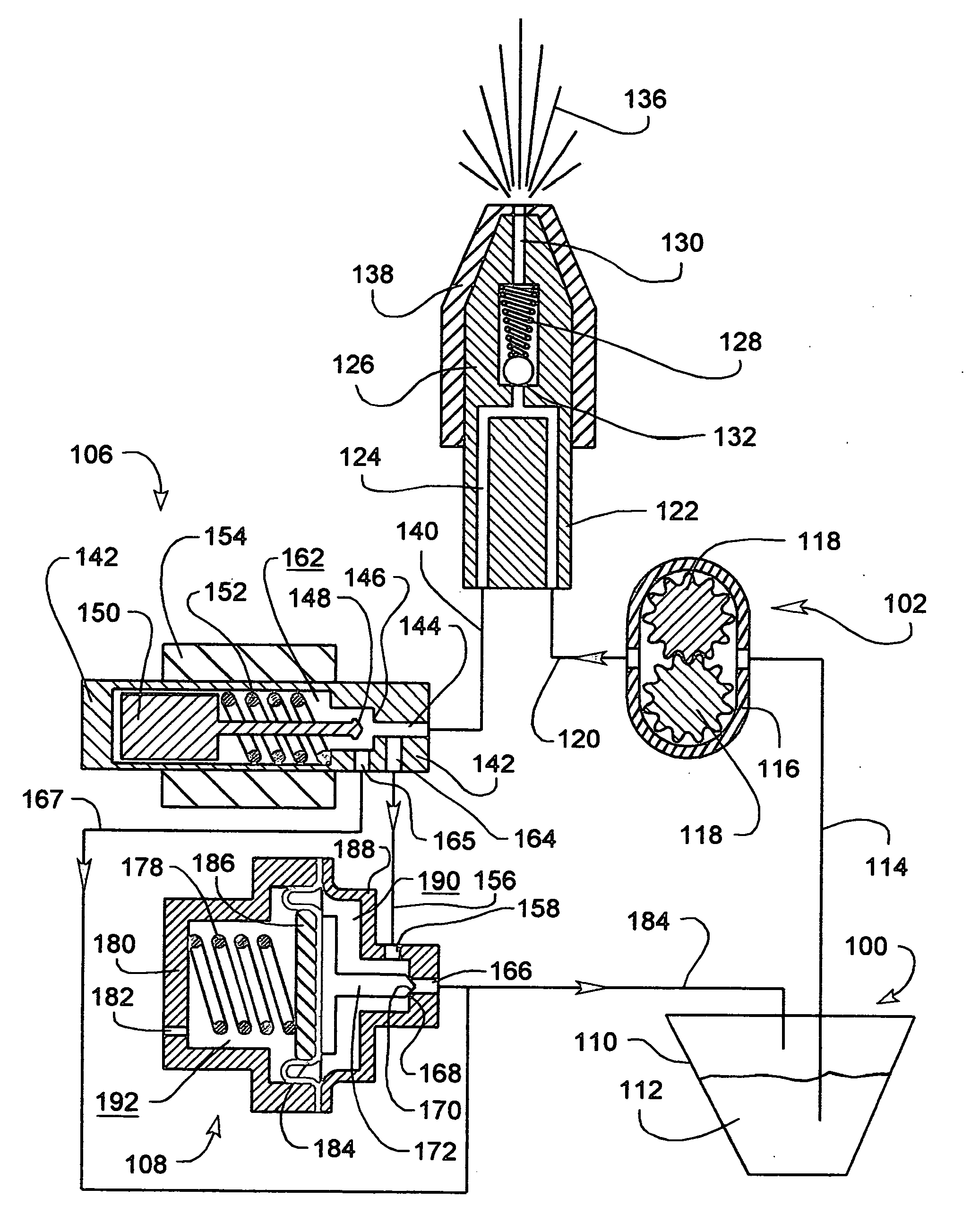
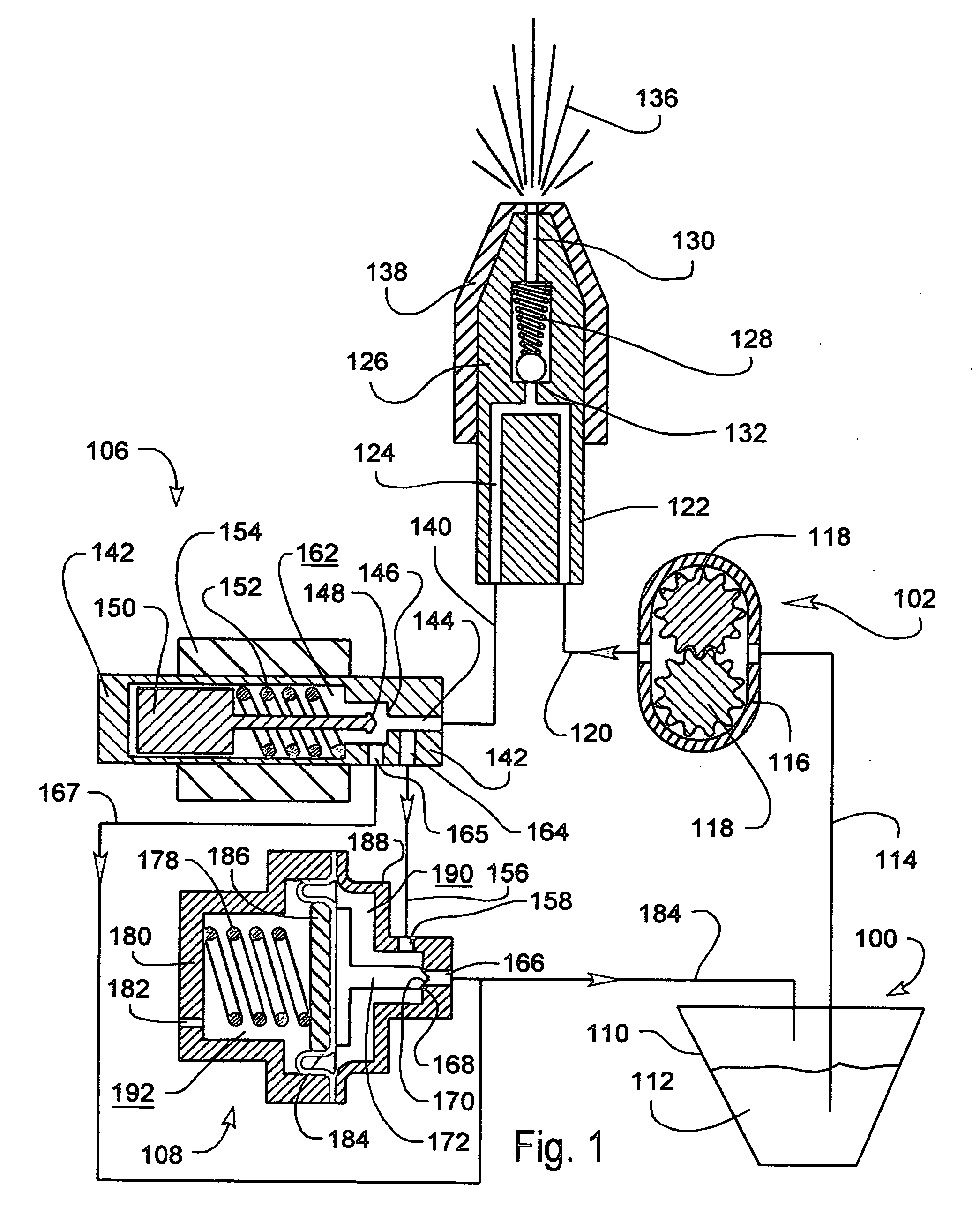
[0013]FIG. 1 is an exemplary schematic representation describing a fluid circuit using a variable orifice and fixed speed pump. A circuit consists of reservoir 100 as the origin communicating through line 114 to pump 102, then communicating through line 120 to spray nozzle 104 then communicating through line 140 to pulse width modulating valve 106, then communicating through line 156 to back pressure regulator 108, and then communicating through line 184 to reservoir 100 as the destination. During normal operation, a portion of a fluid flowing in this circuit is ejected as a spray 136. Back pressure regulator 108 maintains a predetermined spray pressure.

[0014]The following detail is directed toward describing a circuit...


PUM


Abstract

A system for spraying fluids at variable flow rate using pulse width modulation utilizing a circuit including a reservoir, pump, spray nozzle, pulse width modulated valve. While no spray issues from a nozzle, the fluid circuit is closed with the reservoir as the initial and end point of the circuit. While no spray issues from a nozzle, the fluid flow through a heated nozzle functions as a heat sink. While spray issues from a nozzle, the circuit contains a means to maintain a specific fluid pressure. While no spray issues from a nozzle, the circuit pressure is much lower than the spray pressure allowing reduced energy consumption and lessening wear on the pump and motor. This system may be incorporated into a selective catalytic reduction (SCR) system for controlling NOX emissions from diesel engines using a urea-water solution as a fluid.

Description

FIELD OF THE INVENTION[0001]The present invention relates generally to mobile equipment where fluid is dispensed as a intermittent spray. More particularly, the present invention relates to hydraulic circuit of the spray system where the spray rate is controlled by pulse width modulated and there is benefit to reducing the average power consumption of the motor that drives the spray pump. Applications include pollution control such as SCR (selective catalytic reduction) emission control on diesel engines and agricultural uses such as pest control and fertilizer application.BACKGROUND OF THE INVENTION[0002]Many types of equipment use include a means for pumping a fluid from a reservoir and spraying it from one or more nozzles. A paint spray gun is such an example. From a control point of view, a steady state condition where the flow is constant is the simplest case. However, adaptive control is most often needed for reasons of performance and / or economy. Typically, varying the flow r...

Claims


Application Information

Patent Timeline
Patent Type & Authority Applications(United States)
IPC IPC(8): B05B17/00F02M45/00
CPCB05B1/304B05B9/0416B05B12/06Y02T10/24F01N3/2066F01N2610/1453B05B12/088Y02T10/12
Inventor SMITH, CLYDE MERIWETHER
Owner SMITH CLYDE MERIWETHER
Why Eureka
Try Eureka