Power supply system, vehicle with the same, temperature increase control method for power storage device and computer-readable recording medium bearing program for causing computer to execute temperature increase control of power storage device

Active Publication Date: 2009-08-06
TOYOTA JIDOSHA KK
View PDF1 Cites 18 Cited by
  • Summary
  • Abstract
  • Description
  • Claims
  • Application Information

AI Technical Summary

Benefits of technology

[0027]According to the invention, therefore, the temperatures of the first and second power storage devices can be actively and rapidly increa

Problems solved by technology

However, aforementioned Japanese Patent Laying-Open No. 2003-209969 has merely disclosed that the power storage device is operated to charge and discharge uniformly the plurality of batteries

Method used


Image

  • Power supply system, vehicle with the same, temperature increase control method for power storage device and computer-readable recording medium bearing program for causing computer to execute temperature increase control of power storage device
  • Power supply system, vehicle with the same, temperature increase control method for power storage device and computer-readable recording medium bearing program for causing computer to execute temperature increase control of power storage device
  • Power supply system, vehicle with the same, temperature increase control method for power storage device and computer-readable recording medium bearing program for causing computer to execute temperature increase control of power storage device

Examples


Example

First Embodiment

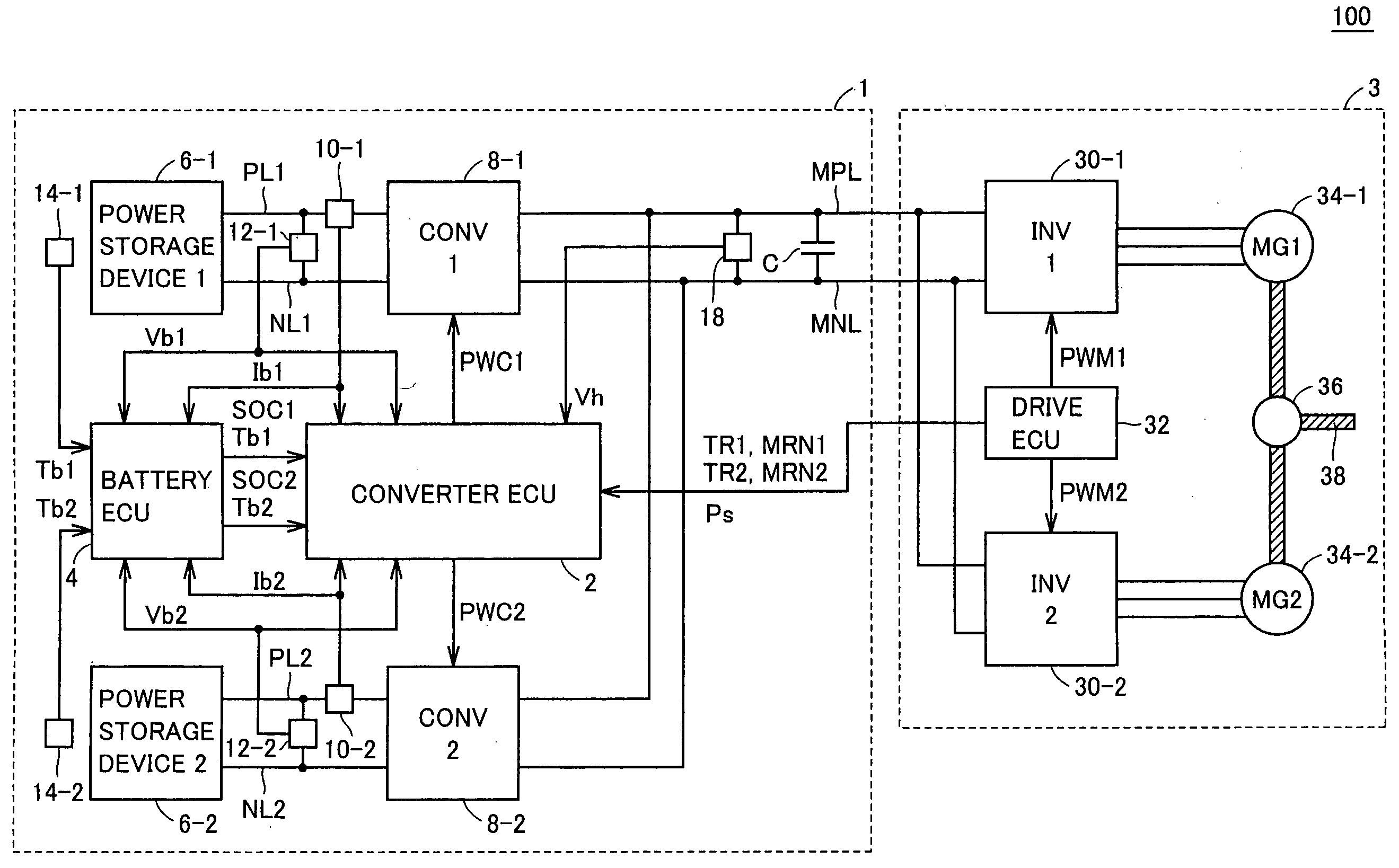
[0041]FIG. 1 is an overall block diagram showing a vehicle of a first embodiment of the invention. Referring to FIG. 1, a vehicle 100 includes a power supply system 1 and a drive power generating unit 3. Drive power generating unit 3 includes inverters 30-1 and 30-2, motor generators 34-1 and 34-2, a power transmission mechanism 36, a drive shaft 38 and a drive ECU (Electronic Control Unit) 32.

[0042]Inverters 30-1 and 30-2 are connected in parallel to a main positive bus line MPL and a main negative bus line MNL. Inverters 30-1 and 30-2 convert the drive powers (DC powers) supplied from power supply system 1 into AC powers, and provide them to motor generators 34-1 and 34-2, respectively. Inverters 30-1 and 30-2 convert the AC powers generated by motor generators 34-1 and 34-2 into DC powers, and provide them as regenerative powers to power supply system 1.

[0043]Each of inverters 30-1 and 30-2 is formed of, e.g., a bridge circuit including three-phase switching eleme...

Example

Second Embodiment

[0096]In the first embodiment, the direction of power transfer between the power storage devices is determined to maximize the power transferred between power storage devices. In the second embodiment, however, the power transfer direction is determined to maximize the heating value of the power storage device.

[0097]A whole structure of a vehicle according to the second embodiment is the same as that of vehicle 100 of the first embodiment shown in FIG. 1. Also, a whole structure of a converter ECU in the second embodiment is the same as that of converter ECU 2 of the first embodiment shown in FIG. 3.

[0098]FIGS. 7 and 8 are flowcharts for illustrating a control structure of a temperature increase control unit 44A in the second embodiment. The processing shown in this flowchart is likewise called for execution from a main routine at predetermined intervals or when a predetermined condition is satisfied.

[0099]Referring to FIG. 7, temperature increase control unit 44A e...

Example

Third Embodiment

[0114]In the first embodiment, the allowable discharge power and allowable charge power are obtained, using the power table, and the power transfer direction is determined based on them to maximize the transferred power quantity between power storage devices 6-1 and 6-2. However, the allowable discharge power and allowable charge power of each power storage device depends on the SOC of the power storage device. According to the first embodiment, therefore, the transferred power quantity takes a currently maximum value in the present operation point, but there may be an operation point where the transferred power quantity can be further increased. According to a third embodiment, therefore, an operation point (i.e., target SOC) where the power mutually transferred between power storage devices 6-1 and 6-2 attains the maximum is obtained, and the charge / discharge of power storage devices 6-1 and 6-2 is controlled to approach the operation point thus obtained.

[0115]FIG....


PUM


Abstract

A power supply system includes power storage devices, converters and a converter ECU controlling the converters. In temperature increase control of power storage devices, converter ECU determines an electric power transferred between the power storage devices via a main positive bus line and a main negative bus line as well as a transfer direction of the electric power, based on an allowable discharge power and an allowable charge power of each power storage device, and controls the converters to transfer the determined electric power between the power storage devices.

Description

TECHNICAL FIELD[0001]The invention relates to a control technique for increasing temperature of a power storage device included in a power supply system.BACKGROUND ART[0002]In recent years, vehicles such as a hybrid vehicle and an electric vehicle that are equipped with an electric motor as a power source have been improved to increase a capacity of a power storage unit for improving drive performance such as acceleration performance and a continuous travel distance. A structure having a plurality of power storage devices has been proposed as means for increasing the capacity of the power storage unit.[0003]Japanese Patent Laying-Open No. 2003-209969 has disclosed a power supply control system provided with a plurality of power supply stages. This power supply control system includes a plurality of power supply stages that are connected in parallel together and supply a DC power to at least one inverter. Each power supply 6stage includes a battery and a boost / buck DC-DC converter.[0...

Claims


Application Information

Patent Timeline
IPC IPC(8): B60L1/00B60L11/18H01M10/44H02J7/04H01M10/60H01M10/615H01M10/625H01M10/633H01M10/637H02J7/00H02J7/10H02J7/34
CPCB60L3/0046Y02T10/7077B60L11/14B60L11/1851B60L11/1875H01M10/441H01M10/5006H01M10/5016H01M10/5022H01M10/5026H02J7/0018H02J7/0022H02J7/1423H02J7/1453H02J2007/143Y02T10/6217Y02T10/7005Y02T10/7022Y02T10/705Y02T10/7055B60L11/123H01M10/625H01M10/615H01M10/637H01M10/633B60L50/61B60L50/16B60L58/27H02J7/143B60L58/12Y02T10/62Y02T10/70Y02T10/7072Y02E60/10H02J7/007192
Inventor ICHIKAWA, SHINJIISHIKAWA, TETSUHIRO
Owner TOYOTA JIDOSHA KK
Why Eureka
Try Eureka