Muting control device, muting control method, and muting control program

a control device and control method technology, applied in the direction of gain control, volume compression/expansion, low frequency amplifier, etc., can solve the problem of attenuating the level of pop noise generated, and achieve the effect of preventing the pop noise and reducing the amount of attenuation

Active Publication Date: 2009-08-06
ONKYO TECH KK
View PDF1 Cites 8 Cited by
  • Summary
  • Abstract
  • Description
  • Claims
  • Application Information

AI Technical Summary

Benefits of technology

[0012]When controlling the audio signal to the mute mode from the unmute mode, it is possible to decrease the amount of attenuation in a stepwise manner by shifting to the unmute mode after the muting circuit attenuates the audio signal by the predetermined amount of attenuatio...

Problems solved by technology

Thus, the muting circuit can attenuate the level of the pop noise...

Method used


Image

  • Muting control device, muting control method, and muting control program
  • Muting control device, muting control method, and muting control program
  • Muting control device, muting control method, and muting control program

Examples


Embodiment Construction

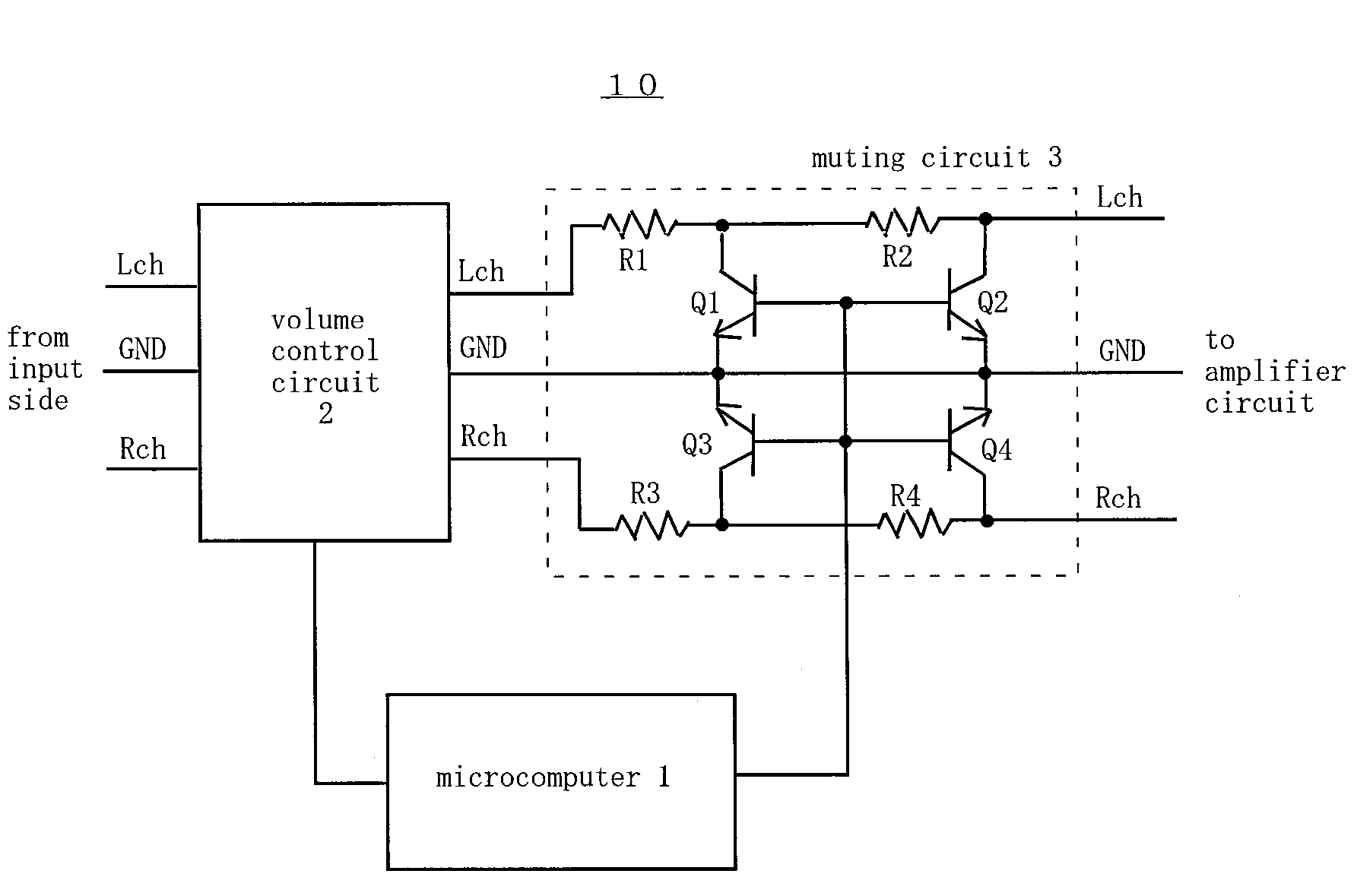
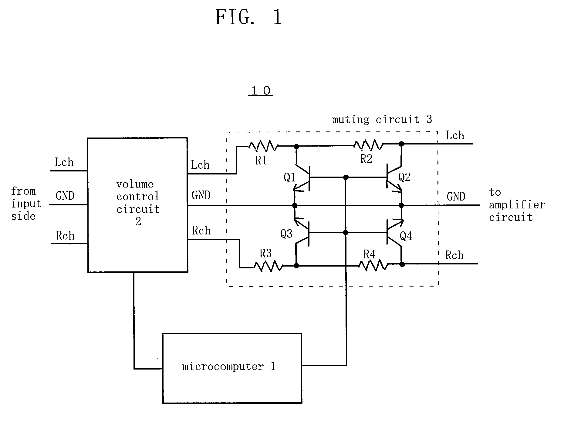
[0017]The following describes a muting control device 10 according to a preferred embodiment of the present invention. However, the present invention is not limited to the embodiment. FIG. 1 is a schematic circuit diagram illustrating the muting control device 10. The muting control device 10 is applied to a device such as an amplifier device, and includes a volume control circuit 2 and a muting circuit 3 that are provided between a circuit on a side from which audio signals are input and an amplifier circuit (not shown), and control section (e.g., a microcomputer) 1 that controls these devices.

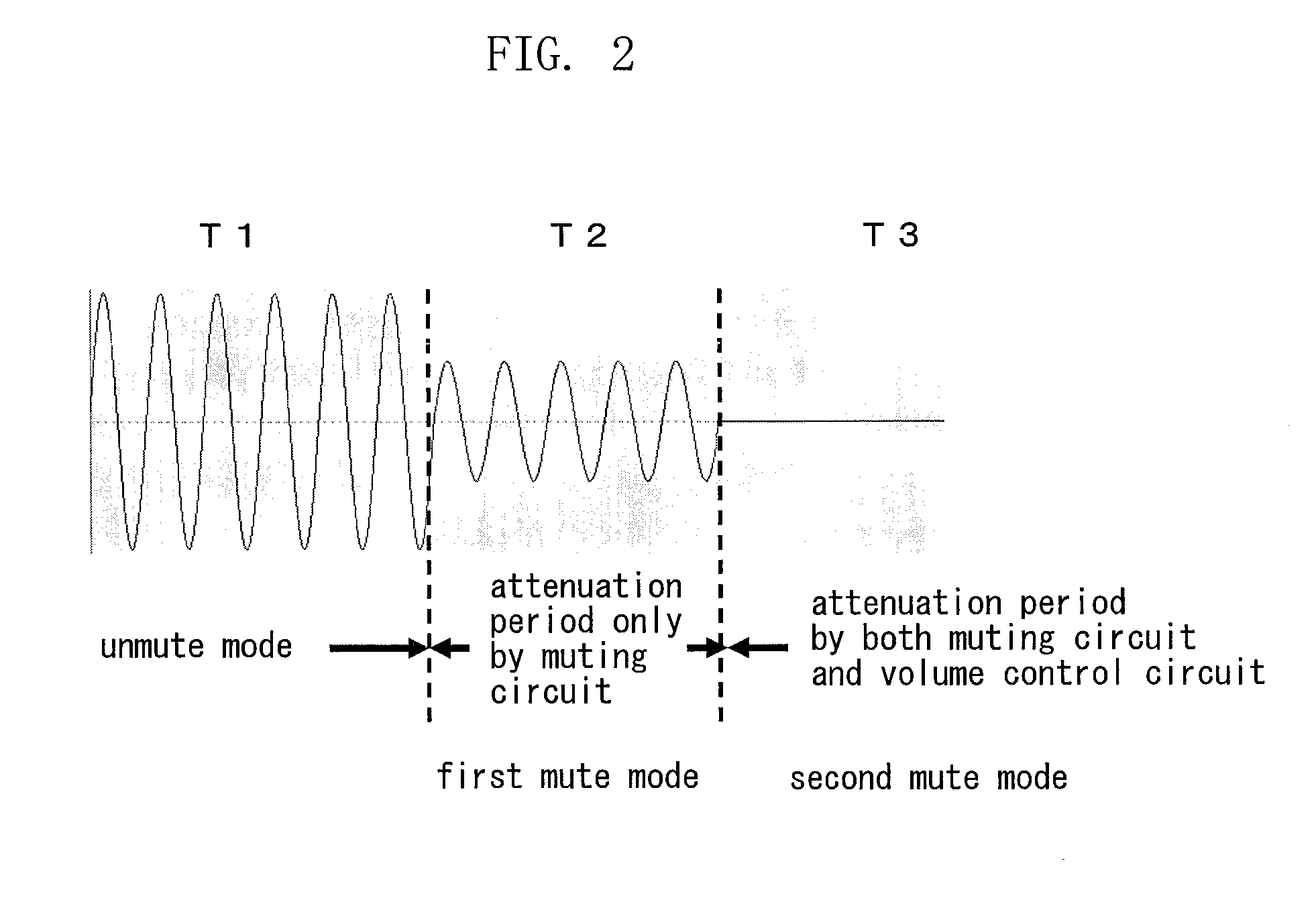
[0018]The muting control device 10 has a mute mode and an unmute mode. In the mute mode, the volume level of the audio signal is attenuated by the volume control circuit 2 and / or the muting circuit 3, thereby setting the volume level of the audio signal either to completely zero, or as close as to zero. The mute mode includes a first mute mode in which only the muting circuit 3 works in the m...


PUM


Abstract

when controlling the audio signal to the mute mode from an unmute mode, first, the muting circuit switches from the non-attenuating state to the attenuating state to cause the muting circuit to attenuate the audio signal by the predetermined amount of attenuation, and then, the amount of attenuation by the volume control section is set to the maximum amount of attenuation to cause the volume control section to attenuate the audio signal by the maximum amount of attenuation.

Description

BACKGROUND OF THE INVENTION[0001]1. Field of the Invention[0002]The present invention relates to a muting control device capable of controlling an audio signal to be in a mute mode.[0003]2. Description of the Related Art[0004]In an audio equipment such as an amplifier device, a volume control device capable of controlling an input audio signal to be in a mute mode and attenuating an audio signal outputted to a subsequent amplifier circuit so that the volume level of the signal is set to zero. Examples of occasions to control the audio signal to be in the mute mode include an occasion where an instruction to control the signal to be in the mute mode is input through a user operation, where the amplifier device is switched to a power-on state from a stand-by state, and where a selector circuit that selects a single audio signal out of a plurality of input audio signals to output the selected signal to the amplifier circuit is switched (e.g., from a tuner to a CD player). The signal is...

Claims


Application Information

Patent Timeline
IPC IPC(8): H03G3/20
CPCH03F1/305H03F3/181H03G3/348H03F2200/211H03G3/34H03F2200/03
Inventor YAMAMOTO, TADASHISHIMOZAWA, DAI
Owner ONKYO TECH KK
Why Eureka
Try Eureka