Eureka AIR delivers breakthrough ideas for toughest innovation challenges, trusted by R&D personnel around the world.

Dermal Scar Treatment Equipment

Inactive Publication Date: 2009-08-06
CHO SI HYUNG
View PDF5 Cites 5 Cited by
  • Summary
  • Abstract
  • Description
  • Claims
  • Application Information

AI Technical Summary

Benefits of technology

[0007]An aspect of exemplary embodiments of the present invention is to address at least the problems and / or disadvantages and to provide at least the advantages described below. Accordingly, an aspect of exemplary embodiments of the present invention is to provide a dermal scar treatment equipment for realizing scar treatment by inserting a plurality of pins into collagen fibers clumping together in the dermis of a scar portion and then propagating a high frequency to the pin-inserted collagen fibers, thus vertically contracting the collagen fibers, reducing a thickness of the dermis, and fragmentizing the collagen fibers.
[0008]Another aspect of exemplary embodiments of the present invention is to provide a dermal scar treatment equipment for preventing a high frequency heat from burning or damaging the epidermis overlying the dermis during a medical treatment process, by forming an insulating layer around pin ends.

Problems solved by technology

As a result, a burn portion of the skin leaves a rough scar of a rugged shape.
However, the fractional laser technology needs a long time to take effect on a hypertropic scar and also, causes side effects of increasing a rate of generation of pigmentation after erythema or inflammation if medical treatment is performed using an increased energy.

Method used


Image

  • Dermal Scar Treatment Equipment
  • Dermal Scar Treatment Equipment
  • Dermal Scar Treatment Equipment

Examples


exemplary embodiment 1

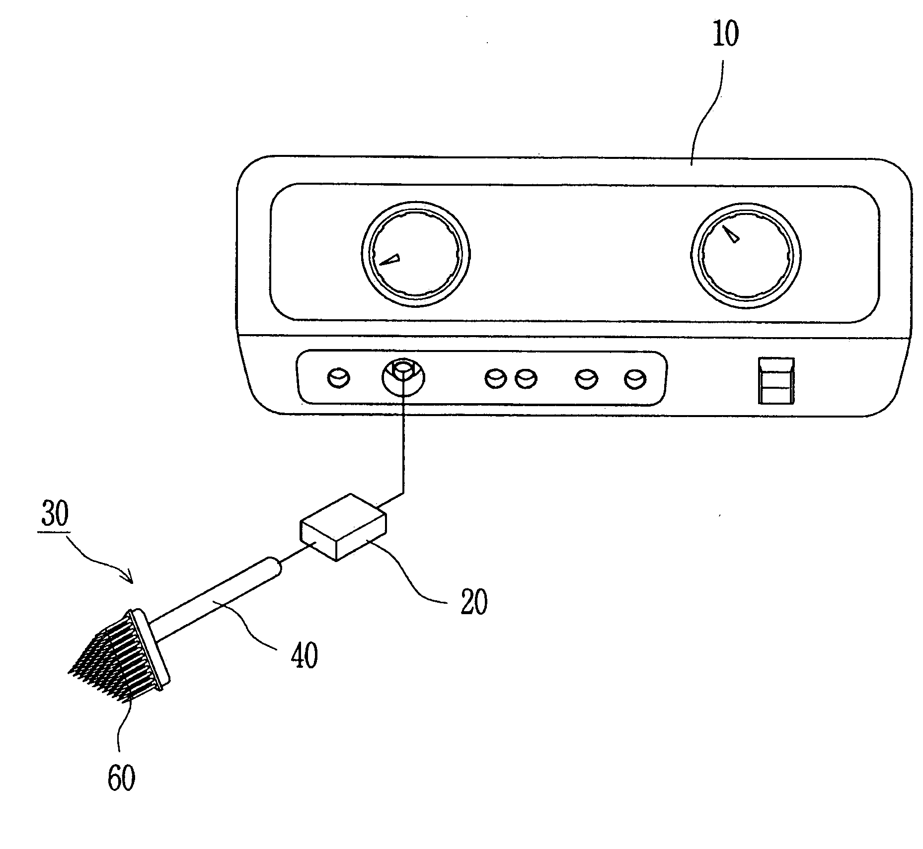
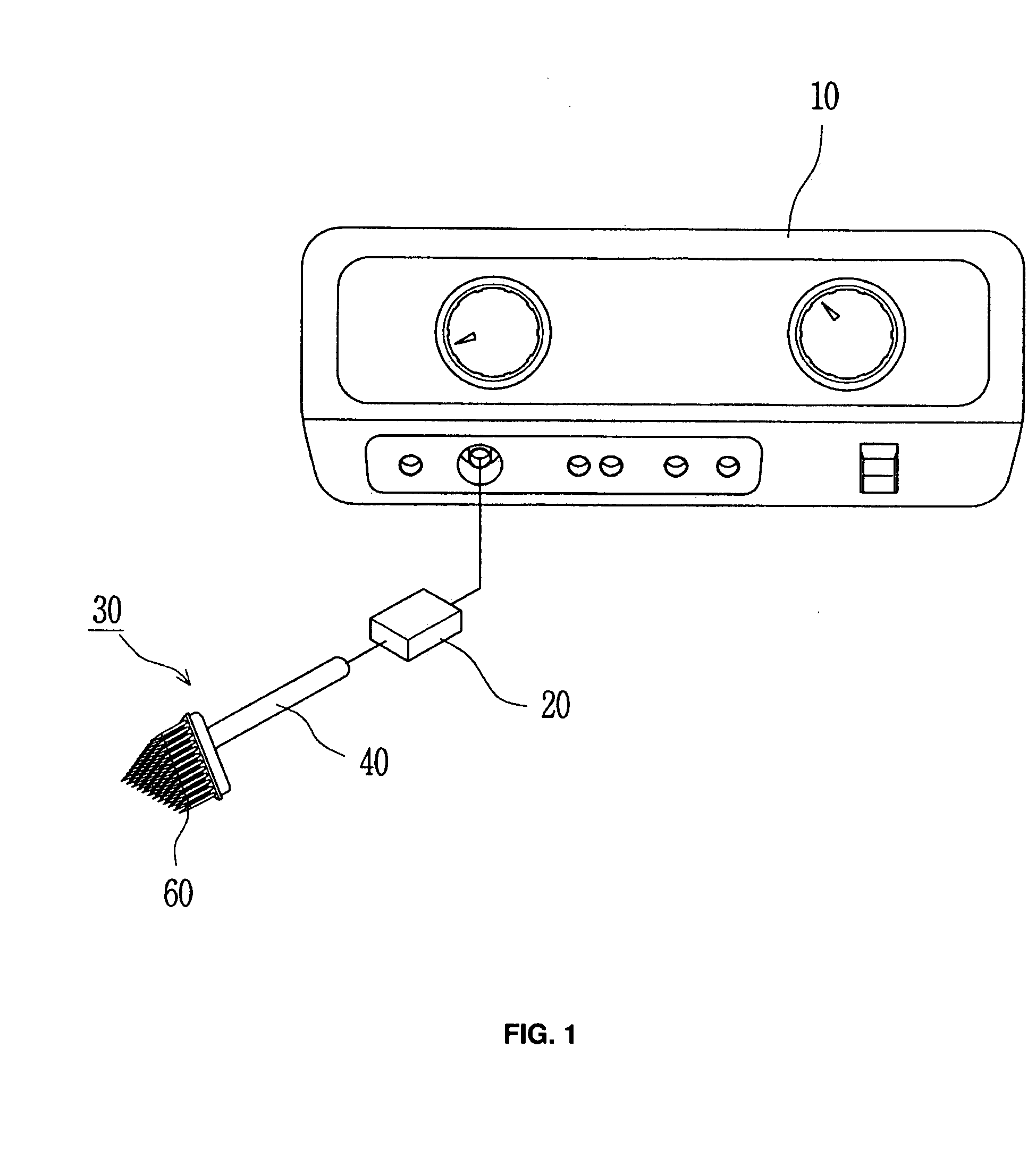
[0021]FIG. 1 is a diagram illustrating the entire construction of a dermal scar treatment device according to the present invention.

[0022]As shown in FIG. 1, the dermal scar treatment device includes a high frequency generator 10, a connector 20, and a dermal scar treatment equipment 30. The connector 20 connects to the high frequency generator 10. The dermal scar treatment equipment 30 detachably electrically connects to the connector 20 and receives a high frequency generated in the high frequency generator 10.

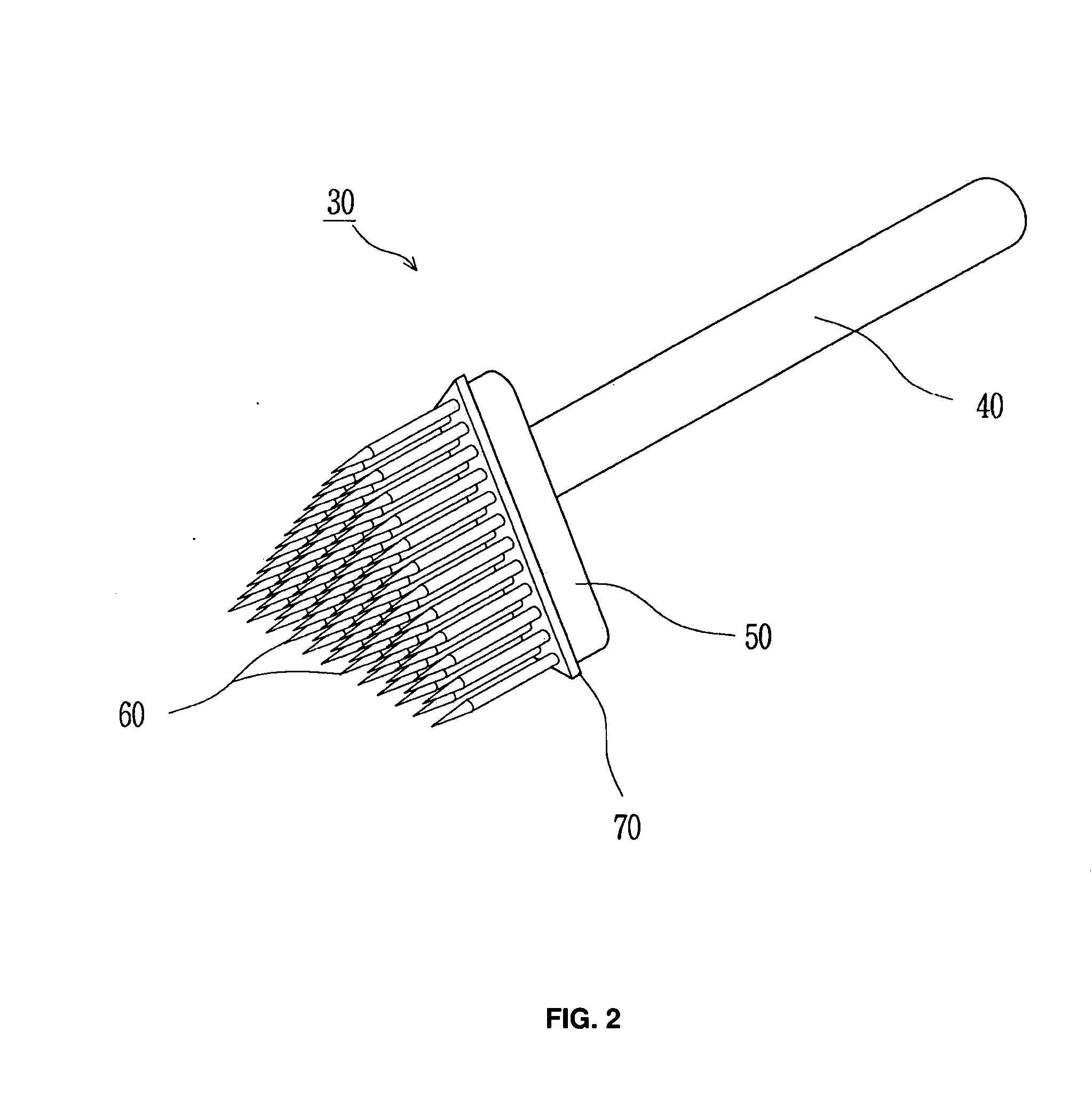
[0023]FIG. 2 is a three-dimensional diagram illustrating a detailed construction of a dermal scar treatment equipment according to an exemplary embodiment of the present invention. FIG. 3 is a diagram illustrating a use state of the dermal scar treatment equipment shown in FIG. 2.

[0024]As shown in FIGS. 2 and 3, the dermal scar treatment equipment 30 includes a rod 40, a flat pad 50, and a plurality of pins 60. The rod 40 is electrically detachably coupled to the connector 2...

experiment example 1

[0030]Objects for treatment were 20 patients suffering a hypertropic burning scar who had visited KIM YANG JE dermatology and BUSAN GOWOON SESANG dermatology that are located at Busan in Korea. The experiment result was obtained from the follow-up observation for one year after surgical operation under patients' approval for clinical trials.

[0031]Surgical operation method for treatment was performed by executing local lidocaine anesthesia for an operation portion having a hypertropic scar, then inserting the pins 60 of the dermal scar treatment equipment 30 into the dermis 200 through the epidermis 100 of the operation portion with the pins 60 standing at right angles, and then applying a high frequency to the pins 60 inserted into the dermis 200 with adhering a front of the pad 50 to the epidermis 100.

[0032]As the experiment result of follow-up observation for one year along with a survey of object patients, it was reported that there was no erythema or Post Inflammatory Hyperpigme...


PUM


Abstract

Provided is a dermal scar treatment equipment. The treatment equipment includes a pad, a plurality of pins, and an insulating layer. The pad electrically connects with a high frequency generator. The pins are protrusively coupled to a front of the pad, are inserted into collagen fibers in the dermis through the epidermis, and propagate a high frequency to the collagen fibers. The insulating layer is coated on an end of each of the pins and isolates the pins from the epidermis for no contact.

Description

FIELD OF THE INVENTION[0001]The present invention relates to a dermal scar treatment equipment, and more particularly, to a dermal scar treatment equipment for realizing scar treatment by vertically contracting collagen fibers in the dermis with no damage to the epidermis of the scar using a high frequency.BACKGROUND OF THE INVENTION[0002]As well-known in the art, skin is composed of the epidermis and the dermis. Below these layers lies a subcutaneous adipose layer. The dermis has a thickness of 1.2 mm to 5 mm.[0003]Collagen fibers in the dermis clump together if skin scars due to a burn and the like. As a result, a burn portion of the skin leaves a rough scar of a rugged shape.[0004]Attempts have been recently made on a diversity of methods for treating such scars. Among the methods, the most representative technology can be a scar treatment equipment using a fractional laser, for example.[0005]The fractional laser technology is based on the principle of making a fine hole in skin ...

Claims


Application Information

Patent Timeline
IPC IPC(8): A61B18/20
CPCA61B18/203A61B2018/00458A61B2018/00452A61N1/06
Inventor CHO, SI HYUNG
Owner CHO SI HYUNG
Why Eureka
Eureka Blog
Learn More