System and method for providing constant loading in ac power applications

a technology of ac power applications and constant loading, applied in the direction of multiple dynamo-motor starters, motor/generator/converter stoppers, dynamo-electric converter control, etc., can solve the problems of uneven loading of generators and power transmission systems, waste of electric motors, and increase harmonic content, so as to achieve constant loading

Active Publication Date: 2009-08-13
THE POWERWISE GRP
View PDF99 Cites 33 Cited by
  • Summary
  • Abstract
  • Description
  • Claims
  • Application Information

AI Technical Summary

Benefits of technology

[0012]Another object of the present invention is to provide a system and method for providing constant loading in AC power applications wherein loading is evenly applied on a generator.
[0028]Another object of the present invention is to provide a system and method for providing constant loading in AC power applications wherein consumption of fossil fuels is reduced.

Problems solved by technology

It is well known that electric motors waste power when not operating at maximum load.
Although phase-chopping does, in fact, reduce energy, the interruption in power by removing the portions cause, among other things, increased harmonic content and un-even loading on a generator and power transmission system.
Due to these effects, optimum utilization of incoming AC power is not achieved.
Any deviation in timing or frequency of the AC power could affect the overall performance of the electrical device.
Under such circumstances, although the overall energy load is reduced, the load across each half cycle is repetitively unbalanced.
The repetitive unbalance of load on each half cycle ultimately results in compromised performance of the electrical devices in which the energy savings device is connected thereto.

Method used


Image

  • System and method for providing constant loading in ac power applications
  • System and method for providing constant loading in ac power applications
  • System and method for providing constant loading in ac power applications

Examples


Embodiment Construction

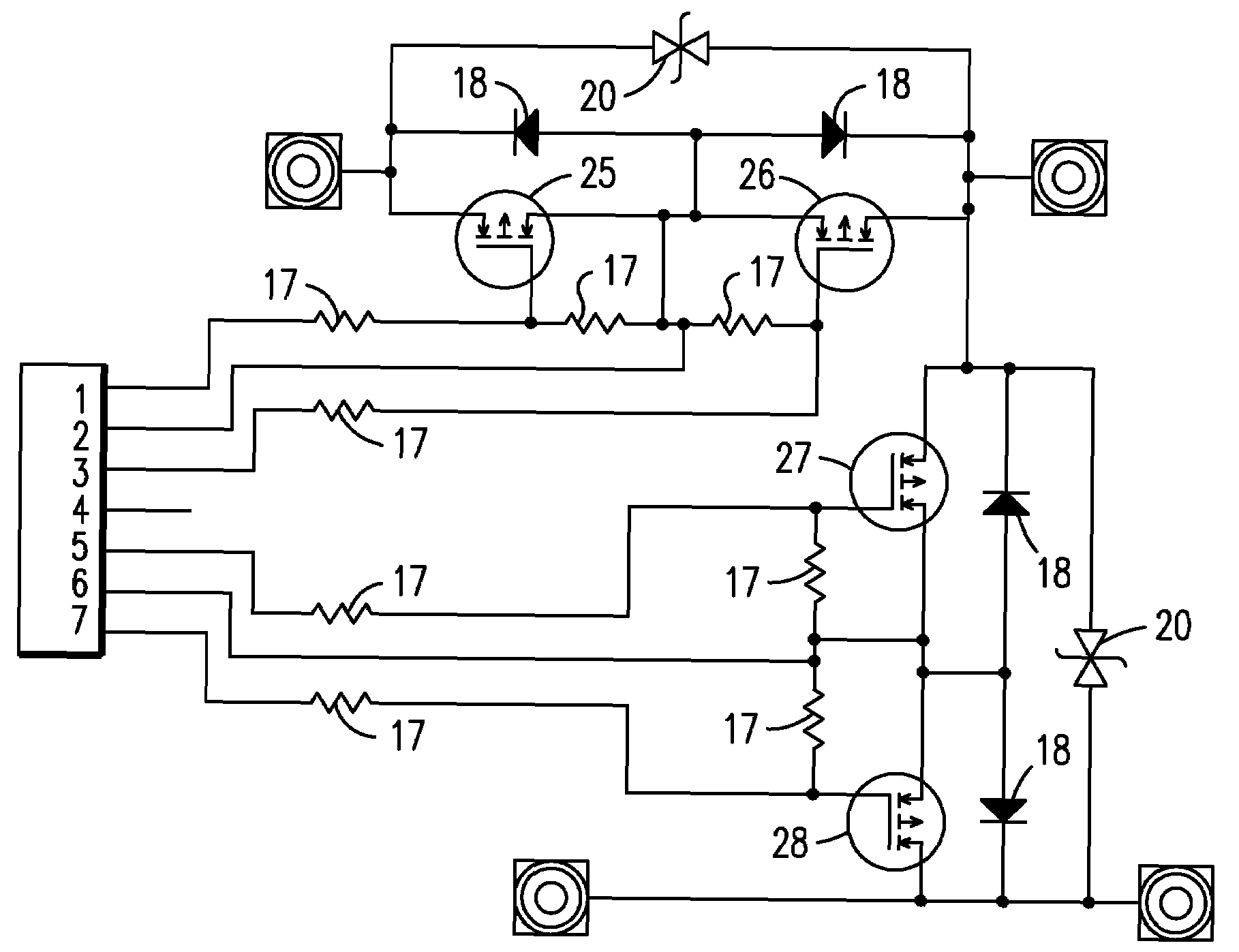
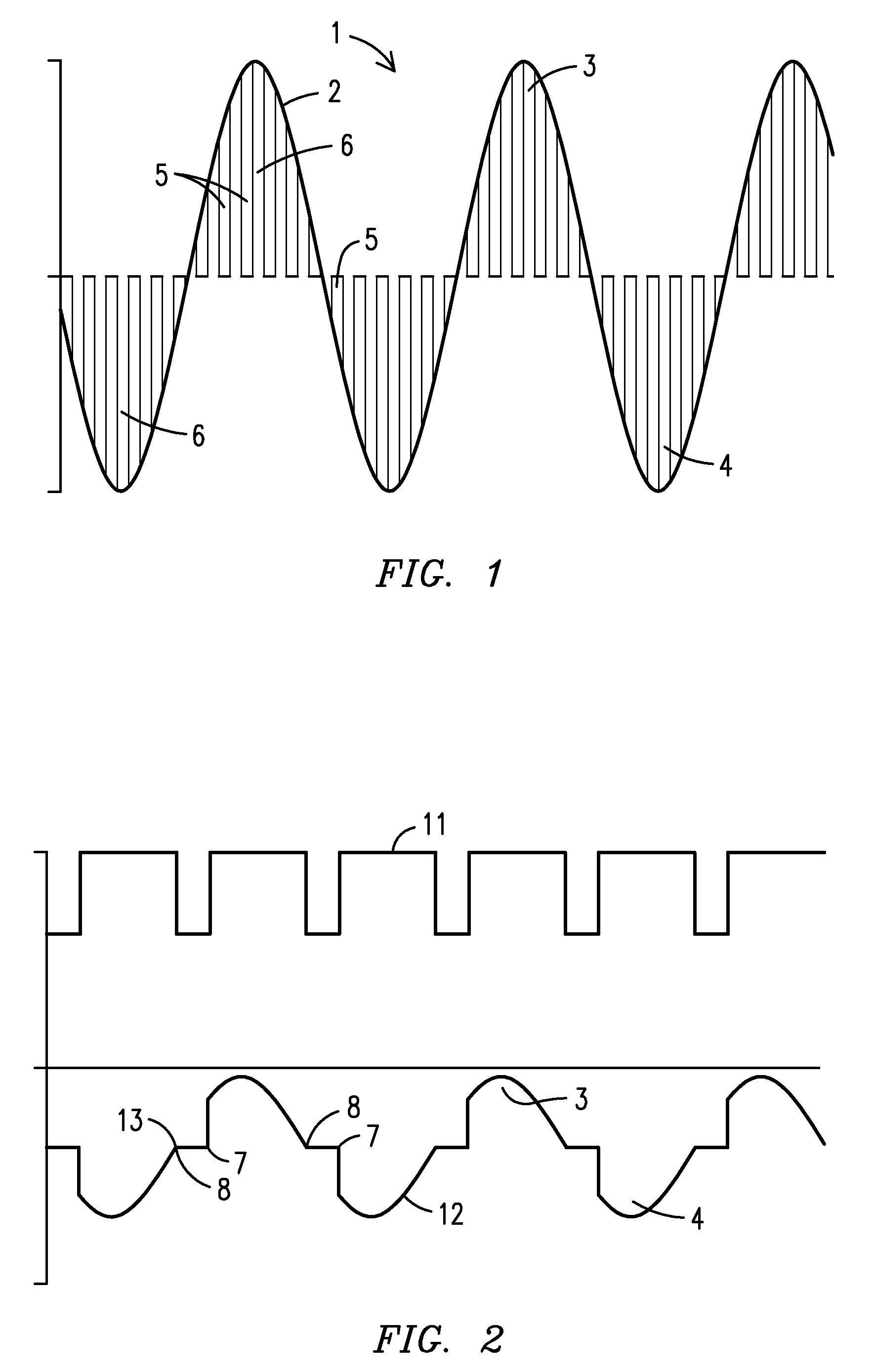
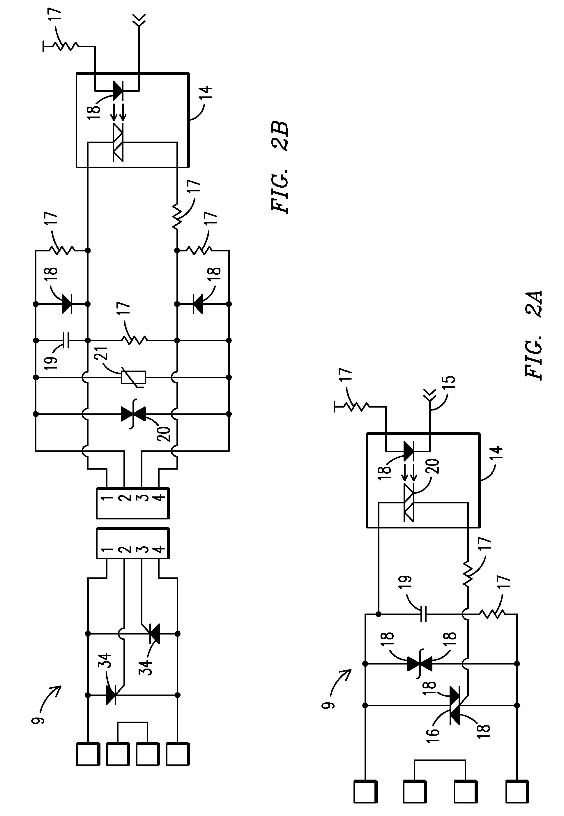
[0045]For purposes of describing the preferred embodiment, the terminology used in reference to the numbered components in the drawings is as follows:[0046]1. constant loading means, generally[0047]2. modulating sine wave[0048]3. positive half cycle[0049]4. negative half cycle[0050]5. slice[0051]6. area[0052]7. turn-on point[0053]8. turn-off point[0054]9. drive control[0055]10. power coordinator[0056]11. modulation drive wave form[0057]12. resultant voltage modulation[0058]13. zero cross point[0059]14. optically-isolated TRIAC[0060]15. terminal[0061]16. main TRIAC[0062]17. resistor[0063]18. diode[0064]19. capacitor[0065]20. transorb device[0066]21. varistor[0067]22. crest[0068]23. network server[0069]24. motor controller[0070]25. positive half cycle control transistor[0071]26. negative half cycle control transistor[0072]27. IGBT first shunt control transistor[0073]28. IGBT second shunt control transistor[0074]29. optically-coupled driver[0075]30. network[0076]31. FET first shunt con...


PUM


Abstract

A system and method for providing constant loading in AC power applications wherein at least one turn-on point (7) of at least one half cycle of a modulating sine wave (2) is determined; at least one turn-off point (8) of said at least one half cycle of a modulating sine wave (2) is determined; and at least one slice (5) located between said at least one turn-on point (7) and said at least one turn-off point (8) is removed. The slices (5) may be removed by utilizing triode alternating current switches, silicone controlled rectifiers, insulated gate bipolar transistors or field effect transistors.

Description

CROSS REFERENCE TO RELATED APPLICATION[0001]This application claims the benefit of U.S. Provisional Application Nos. 60 / 966,197 filed Aug. 24, 2007 and 61 / 009,810 filed Jan. 3, 2008.BACKGROUND OF THE INVENTION[0002]This invention relates to systems and methods for providing constant loading in AC power applications.[0003]It is well known that electric motors waste power when not operating at maximum load. In order to improve the efficiency of such motors and other electronic devices, energy savings devices are commonly employed. Currently, energy savings devices utilize various devices in which to alter an incoming modulating sine wave of an alternating current, which is also known as an AC current. In order to realize an energy savings, direct pulse width modulation (PWM) (or modulation of a pulse carrier wherein the value of each instantaneous sample of a modulating wave produces a pulse of proportional duration by varying the leading, trailing, or both edges of a pulse and which ...

Claims


Application Information

Patent Timeline
Patent Type & Authority Applications(United States)
IPC IPC(8): H02P23/02
CPCH02P23/02
Inventor LUMSDEN, JOHN L.
Owner THE POWERWISE GRP
Why Eureka
Try Eureka