
Local signal generation circuit

a signal generation circuit and local signal technology, applied in the direction of generating/distributing signals, pulse automatic control, instruments, etc., can solve the problems of difficult to generate a wide band signal, increasing etc., to reduce circuit area and power consumption, and high precision

Inactive Publication Date: 2009-08-13
RENESAS ELECTRONICS CORP
View PDF5 Cites 7 Cited by
  • Summary
  • Abstract
  • Description
  • Claims
  • Application Information

AI Technical Summary

Benefits of technology

[0009]A local signal generation circuit in accordance with one aspect of the present invention outputs a frequency-division signal by a prescaler that constitutes a part of a PLL loop. In this way, it is unnecessary to provide an additional frequency divider to generate the frequency-division signal. Therefore, a local signal generation circuit in accordance with one aspect of the present invention can reduce the circuit area and the power consumption.
[0010]A local signal generation circuit in accordance with one aspect of the present invention can control the frequency of the output signal with high precision, while reducing the circuit area and the power consumption.

Problems solved by technology

However, it is generally difficult to generate a wide band signal (e.g., to generate a signal having low phase noise) with a single PLL circuit with high precision.
Since the frequency divider 101 has to be arranged outside of the PLL loop in the PLL circuit 100, there is a problem that the circuit area and the power consumption increase.
Since strict restrictions are imposed on the size of circuit areas and the amount of power consumption in mobile devices and the likes, the increase in the circuit areas and the power consumption becomes a serious problem.

Method used


Image

  • Local signal generation circuit
  • Local signal generation circuit
  • Local signal generation circuit

Examples


first exemplary embodiment

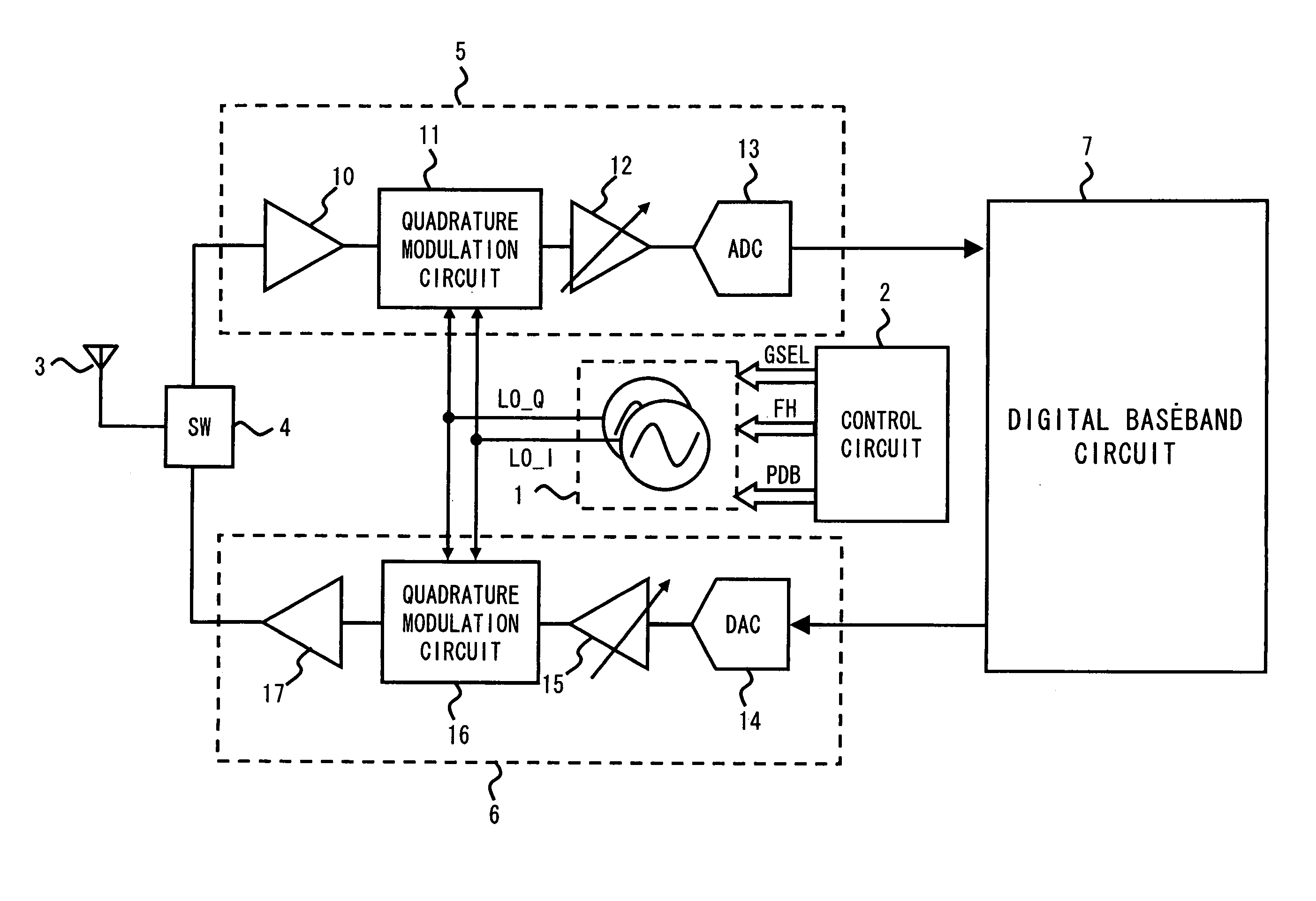
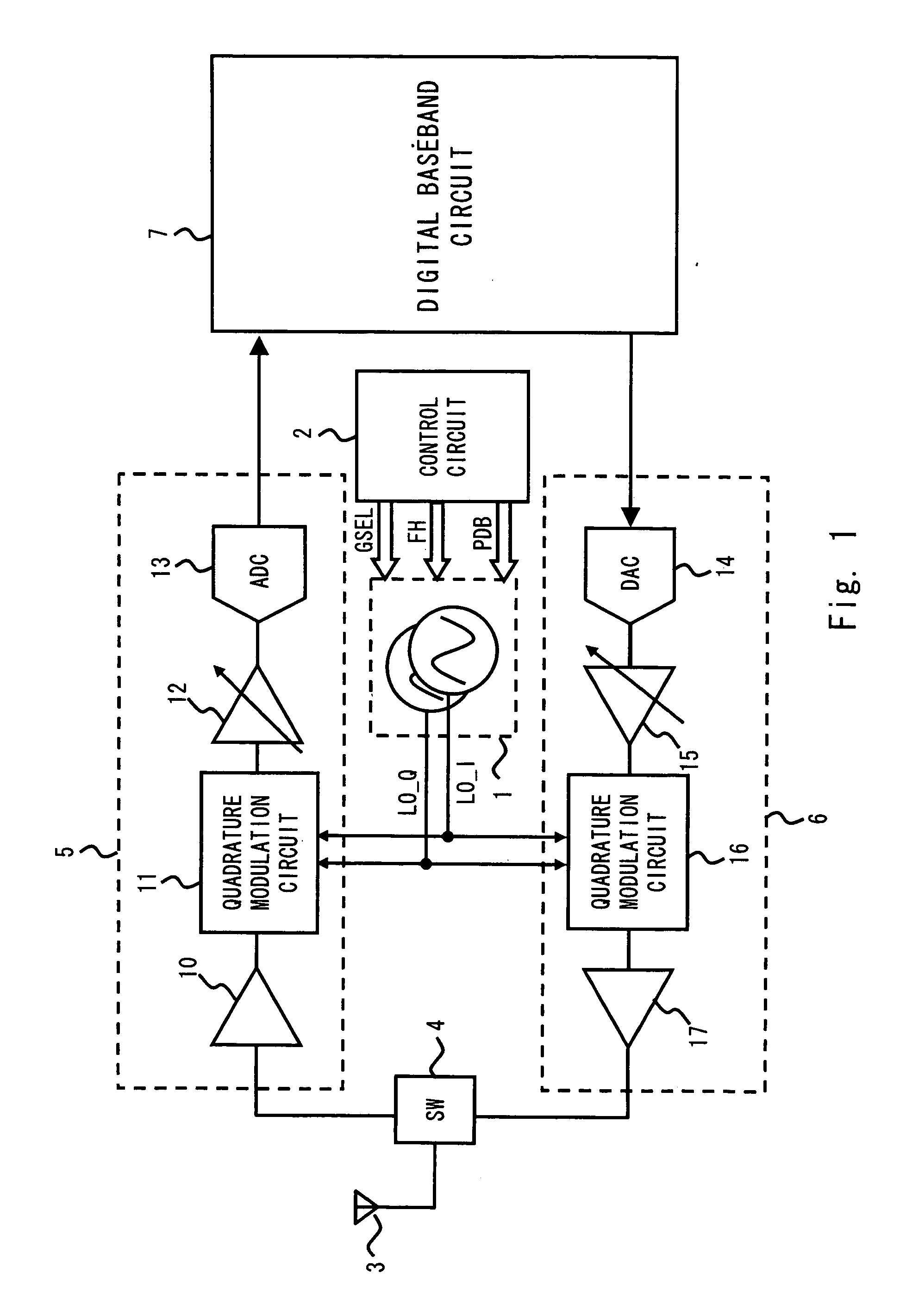
[0021]Exemplary embodiments of the present invention are explained hereinafter with reference to the drawings. FIG. 1 is a block diagram of a transmitter-receiver apparatus having a local signal generation circuit 1 in accordance with an exemplary embodiment of the present invention. As shown in FIG. 1, the transmitter-receiver apparatus includes a local signal generation circuit 1, a control circuit 2, an antenna 3, a switching circuit 4, a receiving circuit 5, a transmitting circuit 6, and a digital baseband circuit 7.

[0022]The local signal generation circuit 1 generates output signals (hereinafter called “local signals”) LO_I and LO_Q. Each of the local signals LO_I and LO_Q is a differential signal, and their phases are different by 90 degrees from each other. That is, the local signals include four signals whose phases are different by 90 degrees from one to another.

[0023]The control circuit 2 generates a band group select signal GSEL, a hopping control signal FH, and a PLL con...


PUM


Abstract

A local signal generation circuit in accordance with one aspect of the present invention includes a phase comparator that detects a phase difference between a reference signal and a feedback signal and outputs a error signal, a charge-pump circuit that receives the error signal and generates a step-up voltage, a loop filter that generates a tuning voltage by changing the shape of the step-up voltage, a voltage control oscillator that generates a first output signal having a predefined frequency based on the tuning voltage, and a prescaler that outputs a second output signal generated by dividing the frequency of the first output signal to a predefined frequency and also outputs a frequency-division signal generated by dividing the frequency of the first output signal to the predefined frequency to a frequency divider that generates the feedback signal.

Description

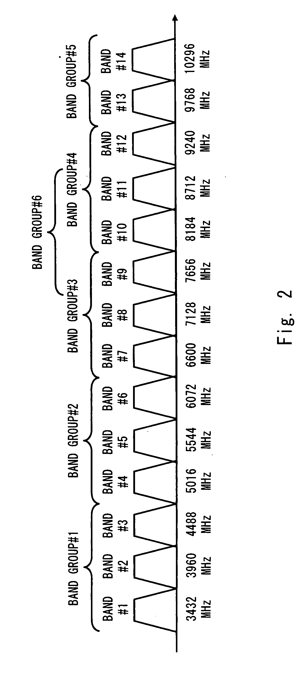
BACKGROUND[0001]1. Field of the Invention[0002]The present invention relates to a local signal generation circuit, in particular a local signal generation circuit having a variable frequency oscillator capable of changing the frequency of the output signal.[0003]2. Description of Related Art[0004]In devices adopting a communication mode based on the UWB (Ultra Wide Band) standard such as the wireless USB (Universal Serial Bus), communication is carried out by dividing a wide band signal (e.g., 3 GHz to 10 GHz) and using a portion of the wide band signal (i.e., a band group having three or two center frequencies). Furthermore, in a communication mode based on the UWB standard, the transmitter side and the receiver side use the same carrier frequency by sharing the carrier frequency in a time-division manner. Furthermore, when a direct conversion configuration is adopted, the device have a local signal generation circuit to generate a local signal having the same frequency as the carr...

Claims


Application Information

Patent Timeline
IPC IPC(8): G06F1/04
CPCH03L7/10H03L7/22H03L7/183H03L7/099H03L2207/06
Inventor KUWANO, AKIRATANAKA, TOSHIYUKI
Owner RENESAS ELECTRONICS CORP
Learn More