
Lithium secondary battery

a secondary battery and lithium battery technology, applied in secondary cell servicing/maintenance, cell components, electrochemical generators, etc., can solve the problems of insufficient charge/discharge cycle characteristics, difficult practicability thereof, and complicated battery configuration, etc., to suppress capacity deterioration, and excellent charge/discharge cycle characteristics

Inactive Publication Date: 2009-08-13
PANASONIC INTELLECTUAL PROPERTY MANAGEMENT CO LTD
View PDF4 Cites 10 Cited by
  • Summary
  • Abstract
  • Description
  • Claims
  • Application Information

AI Technical Summary

Benefits of technology

The present invention provides a lithium secondary battery with a negative electrode containing silicon and tin. This battery has excellent charge / discharge cycle characteristics. The positive electrode contains material that absorbs and releases lithium ions, while the negative electrode contains material containing silicon and tin. When the battery is fully charged, the positive electrode is in a first potentially charged state, while the negative electrode is in a second partially charged state. This combination of charged states helps to prevent capacity deterioration during charging and discharging. Overall, this design provides a lithium secondary battery with excellent charge / discharge cycle characteristics.

Problems solved by technology

However, in lithium secondary batteries using these negative electrode active materials, sufficient charge / discharge cycle characteristics cannot be obtained.
However, as in Patent document 1, when the lithium reference electrode is provided in the battery in order to control the discharge electric potential of the negative electrode using SiO with respect to the lithium reference electrode, the battery configuration becomes complicated, thus making practicability thereof difficult.
Therefore, even if the discharge end voltage is set so that the discharge end electric potential of the negative electrode becomes 0.6 V or less based on the positive electrode, it is difficult to determine whether or not the discharge end electric potential of the negative electrode is maintained to be 0.6 V or less.
Thus, it is difficult to suppress the capacity deterioration associated with the charge / discharge cycle by measuring a battery voltage so as to detect a charge and discharged state of the negative electrode.

Method used


Image

  • Lithium secondary battery
  • Lithium secondary battery
  • Lithium secondary battery

Examples


first exemplary embodiment

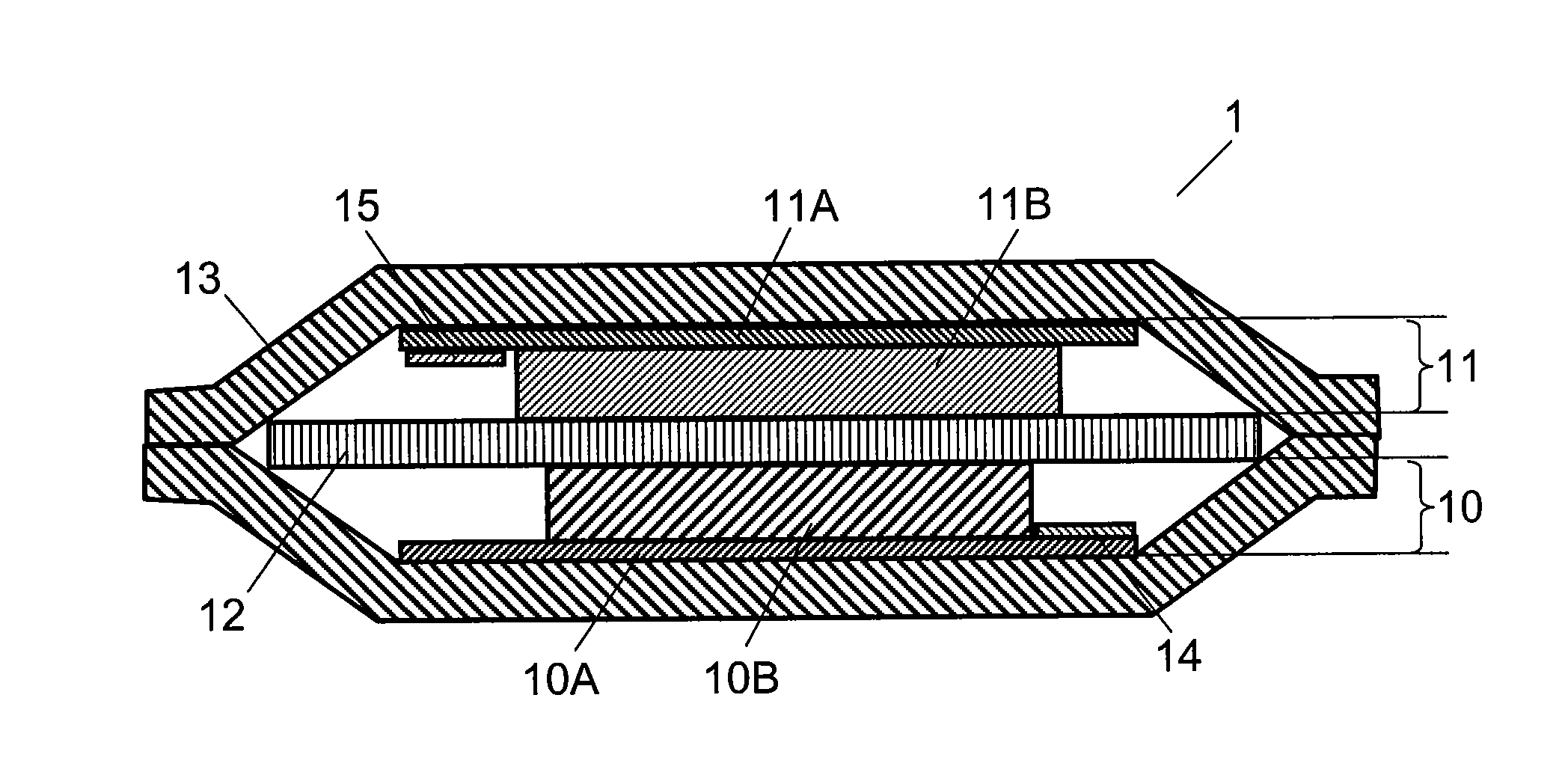
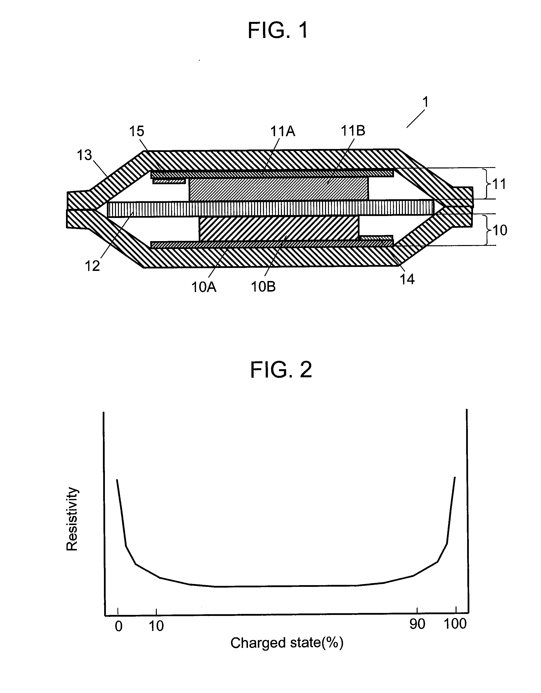
[0027]FIG. 1 is a schematic sectional view showing a configuration of a laminated battery as an example of a lithium secondary battery in accordance with one exemplary embodiment of the present invention. In lithium secondary battery 1, positive electrode 10, negative electrode 11 and separator 12 intervened therebetween are laminated to each other so as to form an electrode group. This electrode group and a non-aqueous electrolyte (not shown) having lithium ion conductivity are accommodated inside outer case 13. The non-aqueous electrolyte is impregnated into separator 12 and interposed between positive electrode 10 and negative electrode 11.

[0028]Positive electrode 10 includes positive electrode current collector 10A and positive electrode active material layer 10B supported by positive electrode current collector 10A. Negative electrode 11 includes negative electrode current collector 11A and negative electrode active material layer 11B supported by negative electrode current col...

second exemplary embodiment

[0055]In this exemplary embodiment, an additive for improving the viscosity of a coating film of a negative electrode active material is added to lithium secondary battery 1. Except the additive, the configuration of the battery and idea of designing the capacity in this exemplary embodiment are substantially similar to those of the first exemplary embodiment.

[0056]As the additive, vinylene carbonate, vinyl ethylene carbonate, fluoroethylene carbonate and the like may be used singly or in combination thereof. These additives may be added to an electrolytic solution as a non-aqueous electrolyte or applied to negative electrode 11 prior to the infusion of the electrolytic solution. Since the use of such additives improves the viscosity of the coating film of the negative electrode active material, the destruction of the coating film when discharge proceeds and the charged state of the negative electrode active material is lowered is suppressed. Due to this, when the second partially c...

example

[0059]Hereinafter, specific examples and the effects thereof are described. Firstly, a production procedure of negative electrode 11 is described. FIG. 10 is a schematic configuration view showing a manufacturing device of a negative electrode for a non-aqueous electrolyte secondary battery in the Example of the present invention. FIG. 11 is a schematic sectional view showing a negative electrode produced by using the device of FIG. 10.

[0060]Manufacturing device 80 includes: vapor deposition unit 85 for forming a columnar body by depositing, on the surface of current collector 11A, material to be vacuum-deposited; gas introducing pipe 82 for introducing oxygen into vacuum chamber 81; and fixing stand 83 for fixing current collector 11A. At the tip of gas introducing pipe 82, nozzle 84 for supplying oxygen into vacuum chamber 81 is provided. These are disposed in vacuum chamber 81. Vacuum pump 86 reduces the pressure inside vacuum chamber 81. Fixing stand 83 is disposed above nozzle ...


PUM

PropertyMeasurementUnit
discharge end voltageaaaaaaaaaa
discharge end electric potentialaaaaaaaaaa

Abstract

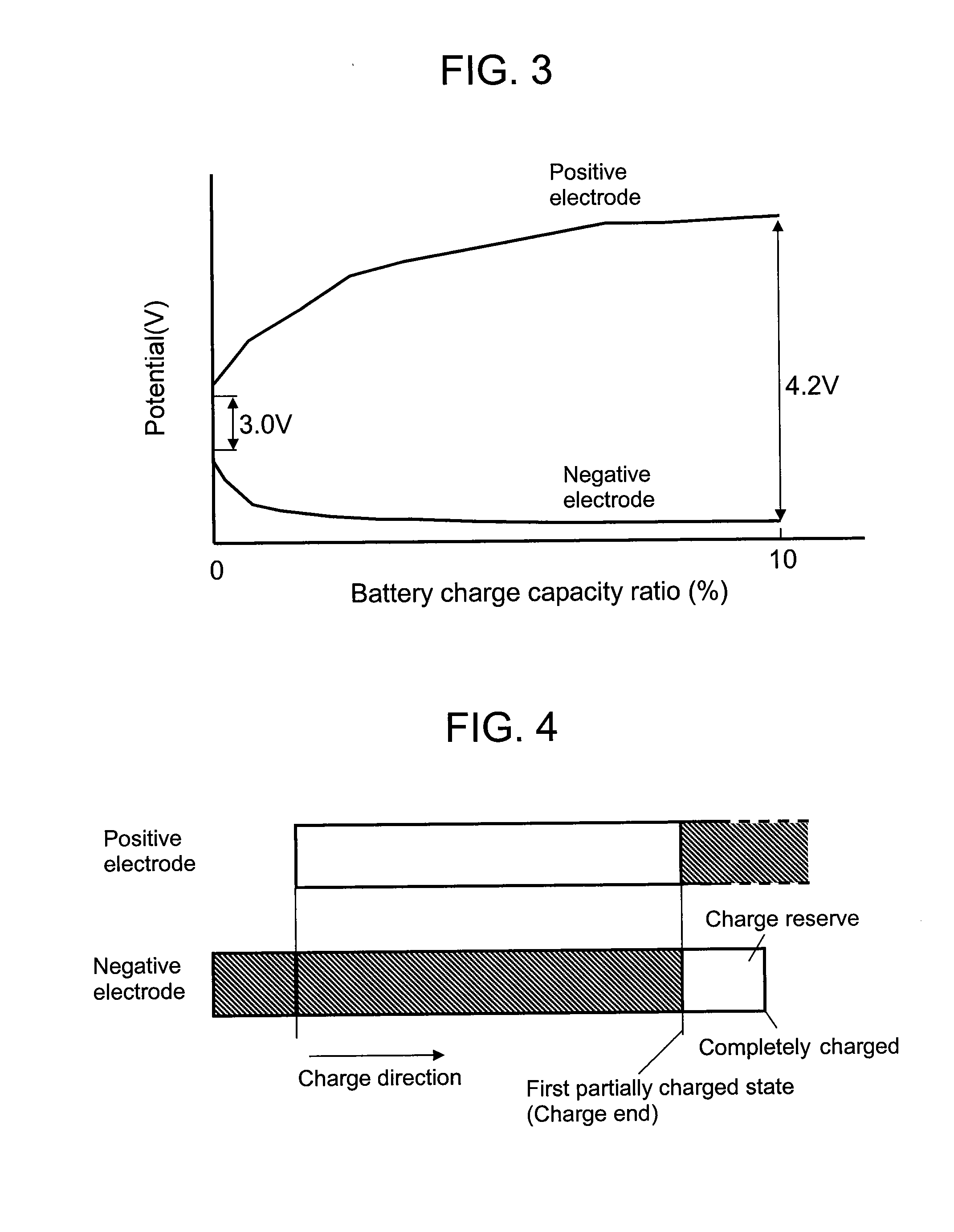
A negative electrode of a lithium secondary battery has a negative electrode active material including at least one element of silicon and tin. Capacities of the positive electrode and the negative electrode of the lithium secondary battery are set as follows. In a completely charged state of the lithium secondary battery charged by a predetermined charging method, the positive electrode active material and the negative electrode active material are in a first partially charged state, respectively. In a completely discharged state of the lithium secondary battery discharged by a predetermined discharging method, the negative electrode active material is in a second partially charged state.

Description

TECHNICAL FIELD[0001]The present invention relates to a lithium secondary battery having an active material including at least one element of silicon and tin in a negative electrode and being excellent in the charge / discharge cycle characteristics.BACKGROUND ART[0002]Recently, with the development of portable devices such as personal computers and portable telephones, batteries as a power source for such devices have been increasingly demanded. The batteries used for the above-mentioned applications are required to be used at ordinary temperatures as well as to have a large energy density and excellent cycle characteristics.[0003]In order to respond to these requirements, for both positive electrode and negative electrode, active materials having a large capacity density have been newly developed. Above all, elemental substances, alloys, or oxides of silicon (Si) or tin (Sn) that can provide an extremely large capacity density are promising materials as negative active materials.[00...

Claims


Application Information

Patent Timeline
Patent Type & Authority Applications(United States)
IPC IPC(8): H01M4/60H01M4/58H01M4/485H01M4/48H01M4/62H01M10/052H01M10/0525H01M10/0567
CPCH01M4/134H01M4/1395H01M4/485Y02E60/122H01M10/0525H01M10/44H01M2004/027H01M10/052Y02E60/10H01M4/02H01M4/48H01M10/05
Inventor UGAJI, MASAYAINOUE, KAORUSHIRANE, TAKAYUKI
Owner PANASONIC INTELLECTUAL PROPERTY MANAGEMENT CO LTD
Learn More