Current collector, electrode, and non-aqueous electrolyte secondary battery

a technology of current collector and electrode, applied in the direction of cell components, final product manufacturing, sustainable manufacturing/processing, etc., can solve the problems of significant changes in the structure of current collector followed by electrode deformation, reduction of electron conductivity between the alloy-based active material layer and the current collector, etc., to achieve excellent charge/discharge cycle characteristics, relieve or disperse stress, and high energy density

Inactive Publication Date: 2009-08-13
PANASONIC CORP
View PDF3 Cites 35 Cited by
  • Summary
  • Abstract
  • Description
  • Claims
  • Application Information

AI Technical Summary

Benefits of technology

[0039]The current collector of the present invention has a structure effective in relieving or dispersing stress generated in association with expansion and contraction of an alloy-based active material. As such, in the electrode of the present invention including the current collector of the present invention and an alloy-based active material layer, cracks of alloy-based active material particles, separation of the alloy-based active material layer from the current collector, and deformation of the current collector followed by deformation of the electrode, and the like hardly occur. This effect is primarily attributable to the structure of the current collector and, for this reason, is unlikely to be reduced even after a long-term use.
[0040]In addition, a non-aqueous electrolyte secondary battery including the electrode of the present invention has a high energy density, is excellent in charge / discharge cycle characteristics, and exhibits little degradation in performance even after a long-term use, and, therefore, is extremely useful as a power supply for various multi-functional portable electronic devices.

Problems solved by technology

However, there is a problem to be solved in such alloy-based active materials, that is, the structure thereof significantly changes during charging when lithium ions are absorbed therein.
In an active material layer containing an alloy-based active material (hereinafter referred to as an “alloy-based active material layer”), the stress generated in association with expansion of the alloy-based active material could easily cause disadvantages such as cracks of alloy-based active material particles, separation of the alloy-based active material layer from a current collector, deformation of the current collector followed by deformation of the electrode, and others.
These disadvantages will then be the cause of the reduction in the electron conductivity between the alloy-based active material layer and the current collector, and the deterioration in the charge / discharge cycle characteristics of the battery.
However, merely increasing the bonding strength between the alloy-based active material layer and the current collector cannot sufficiently absorb the expansion stress of the alloy-based active material, and thus the deformation such as wrinkling and cracking inevitably occurs in the electrode.
Disadvantageously, however, since the gaps are formed by charging in Patent Document 3, it is difficult to obtain evenly-distributed gaps in the thin film of alloy-based active material layer.
As a result, sufficient stress-relieving effect cannot be obtained, and thus the electrode may be deformed.
The disadvantage is that the expansion stress in the columns toward the current collector is concentrated at the interfaces between the columns and the projections or depressions, causing the columns to be easily separated from the surfaces of the projections or depressions.
Accordingly, with the technique disclosed in Patent Document 4, the deformation of the electrode is prevented to some extent, but it is difficult to completely prevent the separation of the columns, namely, the alloy-based active material layer.
As such, the separation of the thin film from the current collector, the deformation of the electrode, and the like will easily occur.
According to this method, it is difficult to uniformly form projections and depressions on the surface of a current collector in its longitudinal and lateral directions since there is a variation in the velocity of the fine particles ejected from the nozzle.
The metallic foil, however, will be subjected to heat higher than the melting point of the metal constituting the metallic foil by laser irradiation.
Because of this, it is difficult to prevent the occurrence of crinkling, wrinkling, warping, and the like on the metallic foil.
In addition, in the case where a metallic foil having a thickness of 20 μm or less, such as a current collector for a lithium secondary battery, is subjected to laser irradiation, disadvantageously, the metallic foil may be perforated because of the variation in the output power of the laser.
The current collector having such projections and depression, during the production thereof, will unavoidably have deformations such as crinkling, wrinkling, and warping.
This may disadvantageously result in tearing of the electrode, and the like.

Method used


Image

  • Current collector, electrode, and non-aqueous electrolyte secondary battery
  • Current collector, electrode, and non-aqueous electrolyte secondary battery
  • Current collector, electrode, and non-aqueous electrolyte secondary battery

Examples


example 1

(1) Production of Current Collector

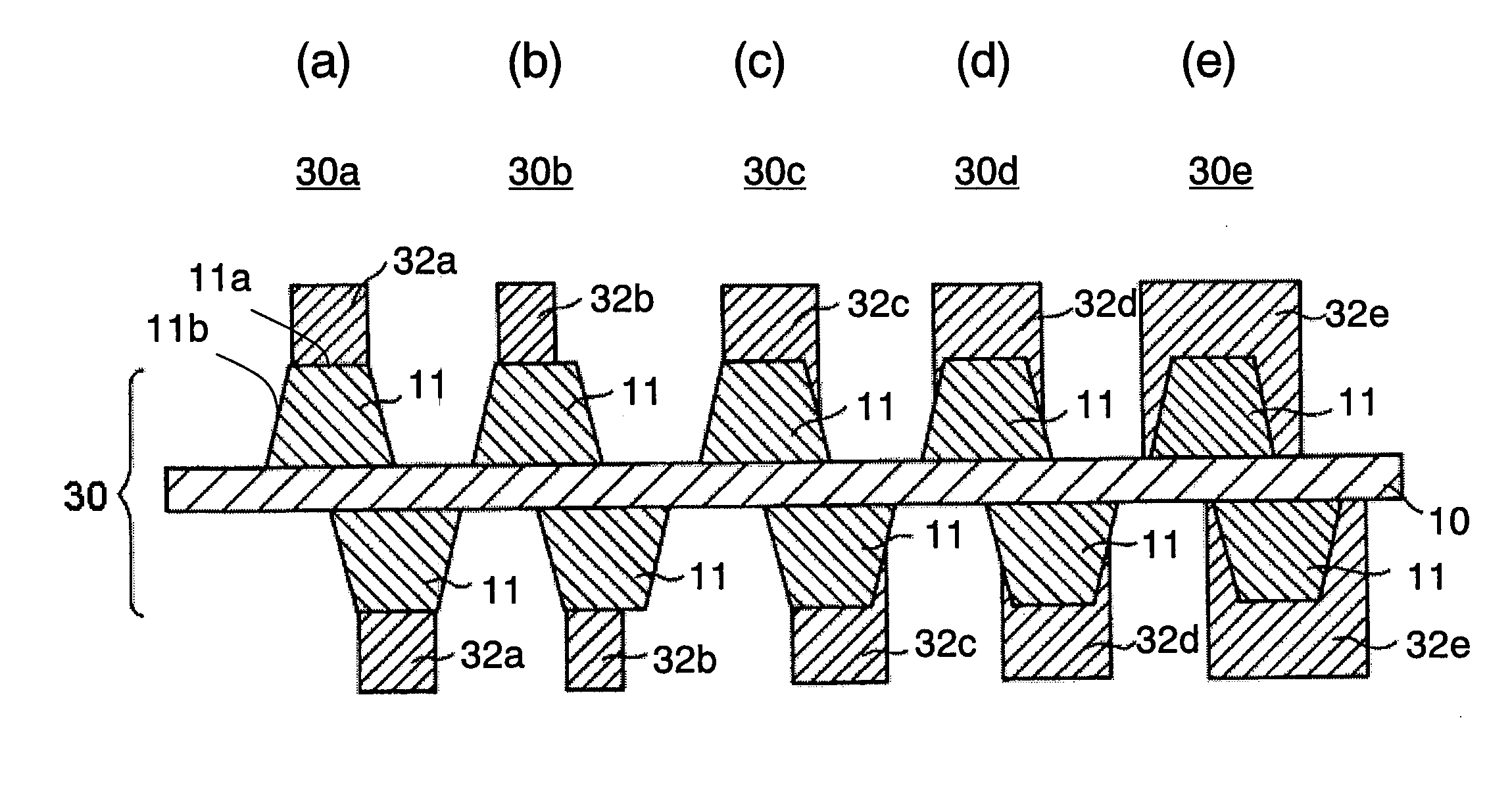
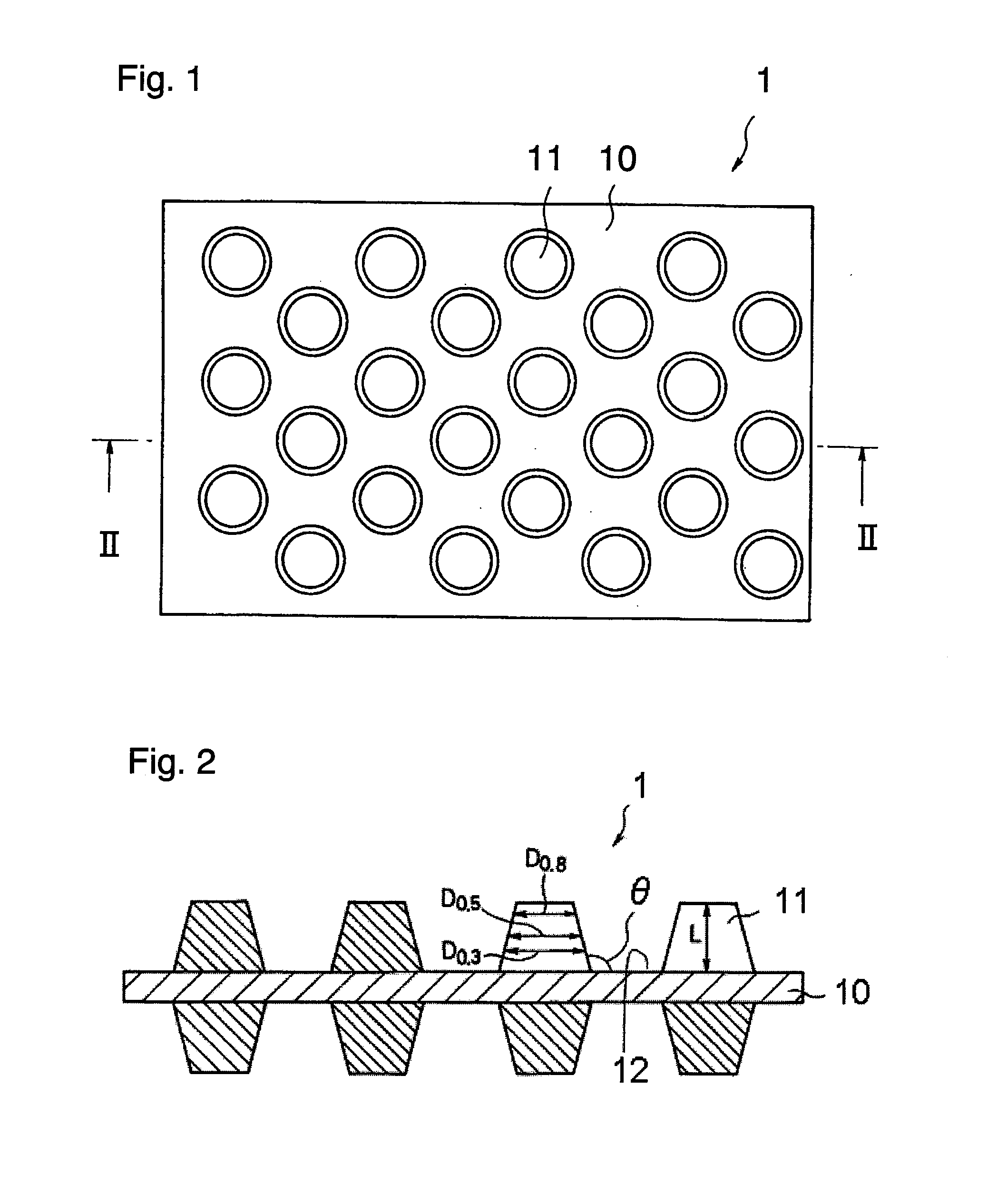
[0169]A ceramic roller with a plurality of recesses formed thereon was mounted as the roller 15 on the current collector production apparatus 20 shown in FIG. 5, the recesses having a depth of 8 μm and being approximately circular in shape with a tapered cross section (bottom diameter: 8 μm, opening diameter: 12 μm). A 15-μm-thick aluminum foil serving as the raw material sheet 23 for current collector was passed through the press nip 21a in the current collector production apparatus 20 under pressure and was subjected to compression and non-compression, whereby a current collector 65 shown in FIG. 13 was produced. FIG. 13 is a set of drawings schematically showing a configuration of the current collector 65 as one embodiment of the present invention. FIG. 13(a) is a top view of the current collector 65. FIG. 13(b) is a longitudinal cross-sectional view of the current collector 65, namely, a thickness-wise cross-sectional view.

[0170]The obtained cu...

example 2

(1) Production of Current Collector

[0177]A ceramic roller with a plurality of recesses formed thereon was mounted as the roller 15 on the current collector production apparatus 20 shown in FIG. 5, the recesses having a depth of 10 μm and being approximately rhombic in shape with a tapered cross section (bottom diameter: 15 μm, opening diameter: 20 μm). A 12-μm-thick copper foil serving as the raw material sheet 23 for current collector was passed through the press nip 21a in the current collector production apparatus 21 under pressure and was subjected to compression and non-compression, whereby a current collector 66 shown in FIG. 14 was produced. FIG. 14 is a set of drawings schematically showing a configuration of the current collector 66 as one embodiment of the present invention. FIG. 14(a) is a top view of the current collector 66. FIG. 14(b) is a longitudinal cross-sectional view of the current collector 66, namely, a thickness-wise cross-sectional view.

[0178]The obtained cur...

example 3

[0184]The non-aqueous electrolyte secondary battery 40 as shown in FIG. 11 was fabricated in the following manner.

(1) Production of Current Collector

[0185]The current collector 65 was produced in the same manner as in Example 1 except that the depth of the recesses formed on the surface of the ceramic roller was changed to 10 μm, and a 18-μm-thick copper foil was used as the raw material sheet 23 for current collector. The obtained current collector 65 was a band of current collector including the base 10 made of copper and approximately circular 8-μm-high projections 11 regularly formed on both surfaces of the base 10 in its thickness direction, the current collector having a total height t2 of 26 μm.

[0186]The arrangement pattern of the projections 11 in the current collector 65 was of a closest-packed arrangement. Therefore, the current collector 65 had a sufficient durability against the tensile stress applied thereto in the longitudinal direction Y. Because of this, in processin...


PUM

PropertyMeasurementUnit
surface roughnessaaaaaaaaaa
elastic modulusaaaaaaaaaa

Abstract

An electrode capable of effectively dispersing or relieving the stress generated in association with expansion and contraction of an active material is provided. The electrode is produced by forming an active material layer on a predetermined current collector. This current collector includes a base and a plurality of projections formed so as to extend outwardly from a surface of the base. The cross section of the projections in a thickness direction of the current collector has a tapered shape in which a width in a direction parallel to the surface of the base narrows from the surface of the base along an extending direction of the projections.

Description

TECHNICAL FIELD[0001]The present invention relates to current collectors, electrodes, and non-aqueous electrolyte secondary batteries.BACKGROUND ART[0002]In recent years, as electronic devices and telecommunication devices have become smaller in size and lighter in weight, the demand for secondary batteries to be used as a power supply for such devices has been increased. Among various secondary batteries, lithium secondary batteries, because of their high capacity, high energy density, and excellent charge / discharge cycle characteristics, have a significantly large market share. Typical lithium secondary batteries are mainly constituted of a negative electrode including a carbon material capable of absorbing and desorbing lithium, and a positive electrode including a composite oxide of a transition metal and lithium, such as LiCoO2. However, in response to the current trend toward more multi-functional electronic devices and telecommunication devices, with respect to such lithium s...

Claims


Application Information

Patent Timeline
Patent Type & Authority Applications(United States)
IPC IPC(8): H01M4/58H01M4/70H01M4/02H01M4/13H01M4/131H01M4/134H01M4/139H01M4/1391H01M4/1395H01M4/38H01M4/48H01M4/66H01M10/052H01M10/058H01M10/36
CPCH01M4/13H01M4/131H01M4/134H01M4/139H01M4/1391H01M4/1395Y02T10/7011H01M4/70H01M10/052H01M10/058H01M2004/027Y02E60/122H01M4/5815Y02E60/10Y02P70/50H01M4/38H01M10/0525
Inventor SUMIHARA, MASANORIITO, SHUJIKOGETSU, YASUTAKAKASHIWAGI, KATSUMIKIRIHARA, NOBUYUKI
Owner PANASONIC CORP
Why Eureka
Try Eureka