Quick-connect splice-free car controller

a car controller and splice-free technology, applied in the direction of coupling device details, coupling device connection, coupling device engagement/disengagement, etc., can solve the problems of dangerous integration task, time-consuming, and inconvenient installation of such devices

Inactive Publication Date: 2009-08-13
FIFELSKI JACOB WALT +1
View PDF10 Cites 63 Cited by
  • Summary
  • Abstract
  • Description
  • Claims
  • Application Information

AI Technical Summary

Problems solved by technology

Although incredibly popular and convenient, the installation of such devices is far from convenient, requires expertise installers, and is time consuming.
With vehicle electrical systems becoming more advanced the task of integration has become dangerous and jeopardizes the vehicles computer system.
The removal of the factory wire insulation by the installer to install the electrical equipment causes irreversible damage.
Corrosion will take place with the wire being exposed to the elements.
Corrosion will lead to poor electrical conductivity which will increase the resistance of the wire, which ultimately will affect voltage and amperage travel in the wire which will indefinitely lead to circuit failure or even electrical fire.
The vehicle environment is prone to moisture, especially where these vehicle electronics such as GPS, remote starters and telemetry products are located and installed-under the dash by the foot pedals, which day in and day out collect moisture from the users' footwear on days with precipitation—snow or rain.
With time, this tape can work loose, the installer can put an inadequate amount of tape on the splice, or may neglect to put any electrical tape on the splice, all of which expose the bare wire which could lead to an electrical short.
Such a short could also lead to fire and serious damage.
Aside from the conductivity shortcomings of manual spices, comes the variable of human error.
Vehicles vary by make and model and even by year which creates confusion and also complicates the installation p...

Method used


Image

  • Quick-connect splice-free car controller
  • Quick-connect splice-free car controller

Examples


Embodiment Construction

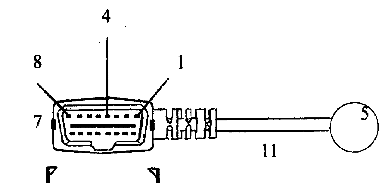
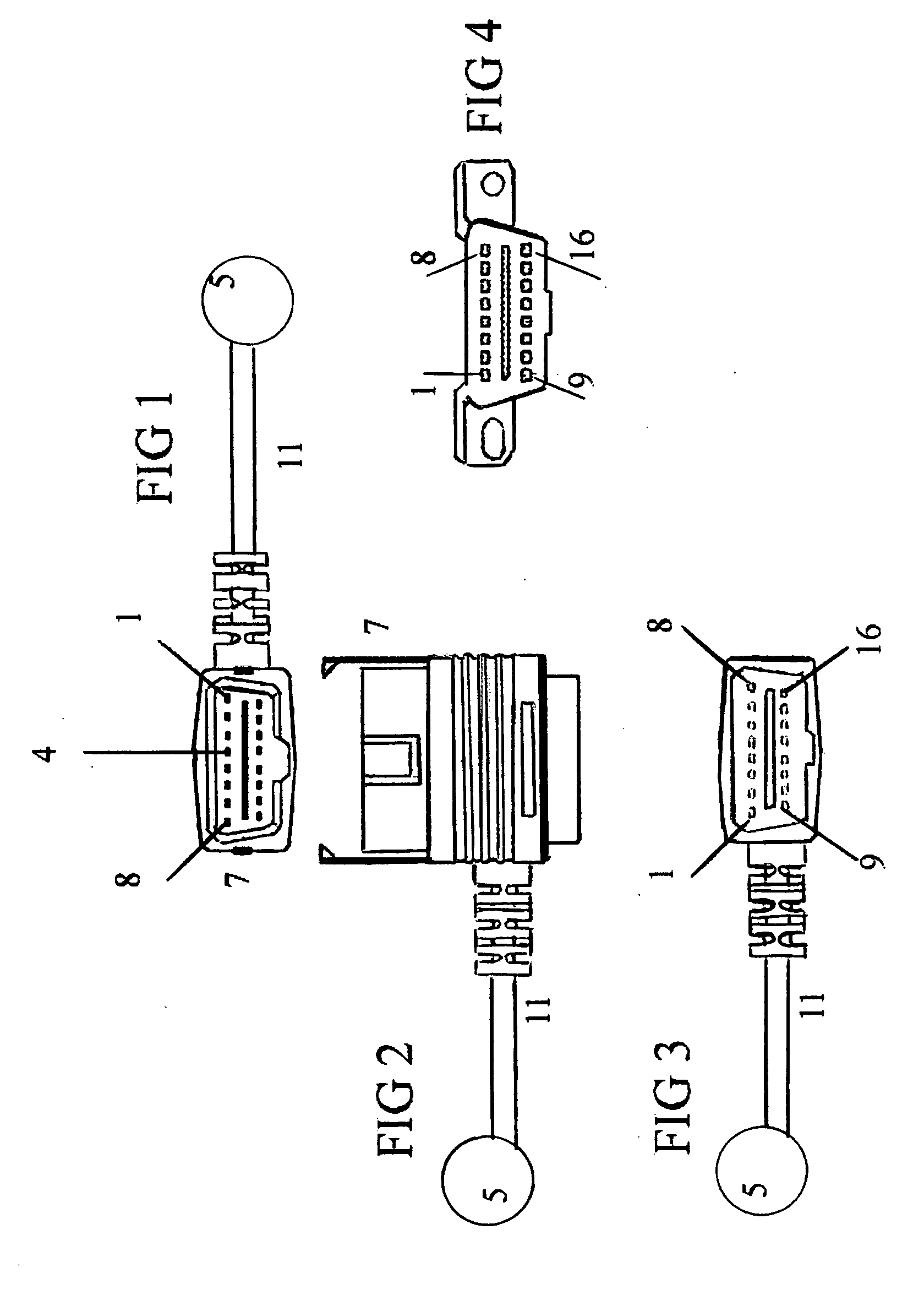
[0036]One embodiment of the quick-connector car controller is illustrated in FIG. 1 which is a front view of the connector with controller 5. Pin number one 1 is shown in the upper right of the connector and will define the top of the connector opposed to the bottom of the connector. Pin number one 1 also defines a left from right with pin number one 1 being the left of the connector when inserted into the OBD-II J1962 female connector show in FIG. 4 which is the view one would witness if looking directly at the OBD-II J1962 female connector installed within the vehicle from the factory. Retaining clip 7 is located on either side of the quick-connector and extend away from the quick-connector to retain connection with OBD-II J1962 connector by reaching around backside of OBD-II J1962 female connector located in the car and forming a grip behind the backside of the connector to prevent dislocation between quick-connect and OBD-II J1962 female connector, in an alternative embodiment i...


PUM


Abstract

The quick-connect splice-free connector establishes a connection between controller 5 with wires terminating at the OBD-II J192 female connector within the car where the pin-out locations are standardized regarding the pins electrical polarity and function, selected from the group of predetermined pin locations providing battery voltage, chassis ground, signal ground, J1850 Bus+, CAN High J-2284, ISO 9141-2 K Line, CAN LOW J-2284, and ISO 9141-2 L Line, and in accordance to these pin-outs, chassis ground pin 4 and battery voltage pin 16 are shown on FIG. 1. The quick-connect splice free connector offers many advantages to the lay person in that a professional installer is not required and all vital electrical signaling lines are readily available through the connector, thus eliminating human error, automobile computer system damage, and complexities of the install by providing controller 5 with direct and safe access to all signaling paths.

Description

CROSS-REFERENCE TO RELATED APPLICAIONS[0001]This application claims priority under 35 U.S.C. .sctn.119(e) of U.S. provisional patent application Ser. No. 61 / 027,816, filed 2008 Feb. 11 by the present inventor.FEDERALLY SPONSORED RESEARCH [0002]Not ApplicableSEQUENCE LISTING OR PROGRAM [0003]Not ApplicableBACKGROUND[0004]1. Field of Invention[0005]This invention relates to automotive electrical systems, specifically how the electrical and computer systems can be controlled through the on-board diagnostics-II, OBD-II, standardized J1962 female connector where a quick-connect splice-free connector and controller can be easily connected and connection retained for communicating through the five protocols used with the OBD-II interface to remotely control motor vehicles eliminating the need to physically and manually splice wires within an automobile to integrate controller. [0006]2. Prior Art[0007]Controllers, namely remote control of vehicles dates back to a time where users first remo...

Claims


Application Information

Patent Timeline
IPC IPC(8): H01R13/62
CPCH01R13/6273H01R2201/26H01R23/10
Inventor FIFELSKI, JACOB WALTBELLGRAPH, VERNON ANDREW
Owner FIFELSKI JACOB WALT
Why Eureka
Try Eureka