Bend-capable stent prosthesis

a stent and bending technology, applied in the field of stent prosthesis, to achieve the effect of ensuring the stent is bending and bending performance, ensuring the stent is bending

Active Publication Date: 2009-08-13
CR BARD INC
View PDF99 Cites 31 Cited by
  • Summary
  • Abstract
  • Description
  • Claims
  • Application Information

AI Technical Summary

Benefits of technology

[0016]A stent construction in accordance with the invention is only marginally more complex than the simple and “classic” zig-zag stenting ring construction evident from drawing FIGS. 1 to 3. The stenting rings can be a simple zig-zag construction of struts all the same length, and the connector portions can be nothing more than a plane of abutment between abutting points of inflection in adjacent zig-zag stenting rings, or simple, short, straight portions aligned with the longitudinal axis of the prosthesis. This is advantageous, when it comes to modelling the fatigue performance of the stent, something of significant importance for government regulatory authorities and for optimising stent performance long term.
[0017]There is another valuable performance enhancement that the present invention can deliver, namely attainment of full performance of any particular “theoretical” stent matrix. In reality, every placement of a stent is an individual unique event. To some extent, every stent of shape memory alloy has had its remembered shape set in a unique heat treatment step. Referring back, once again, to WO 01 / 32102, we set the remembered shape before removing bridges of “scrap” material between stenting rings. In consequence, remembered shapes are highly orderly and regular, much closer to the “theoretical” zig-zag shape than can be attained when the rings are only connected by a minimum of connectors during the shape-setting step. We can have this advantage also with stents in accordance with the present invention, to optimise the bending performance of the stents, and the fatigue resistance that comes from having stress distributions close to optimal, every time.

Problems solved by technology

A small axial gap might therefore suffice, in the delivery disposition of a stent while being inadequate to prevent head to head impact in the expanded disposition.

Method used


Image

  • Bend-capable stent prosthesis
  • Bend-capable stent prosthesis
  • Bend-capable stent prosthesis

Examples


example

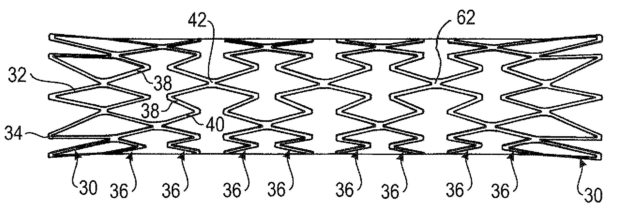
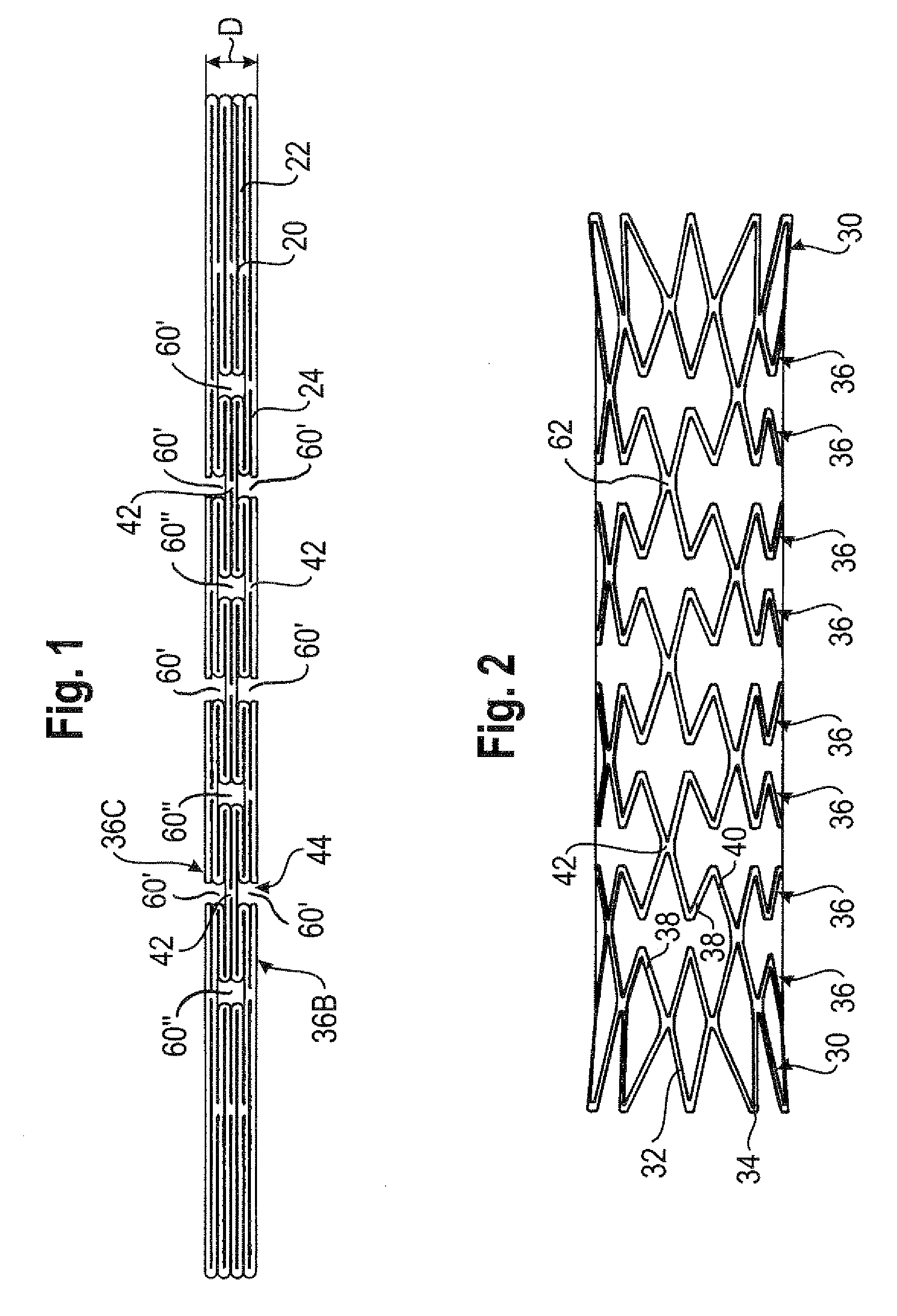
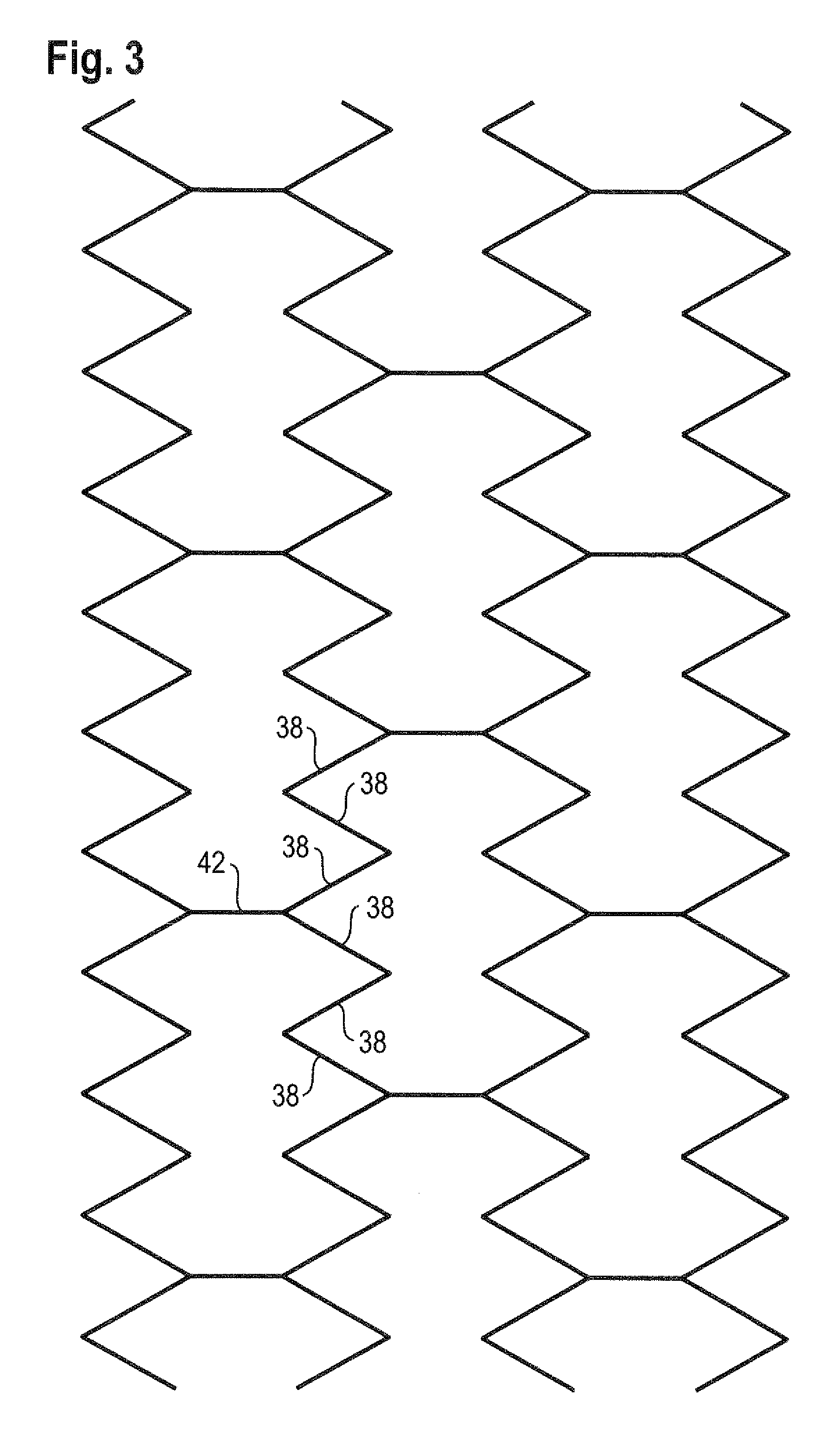
[0047]To assist readers to grasp the physical dimensions of stents that are preferred embodiments of the present invention, we set out in the Table below some representative dimensions for stents studied by the Applicant. It is to be understood that these dimensions are provided not to signify precise dimensions that work better than others but merely dimensions within the ranges here contemplated.

TABLEEach zig-zag ringConnectorStrutStrutextendedNumber ofwidthlengthConnectorlengthProductstruts (μm)(mm)(mm)length(mm)*A241601.950.81.4B361001.450.51.0C301001.450.51.0D321351.550.51.0*This is the full length that lies between the ends of two co-linear slits axially spaced from each other that create the two axially-facing V-points of inflection of two adjacent zig-zag rings

[0048]One message to be taken from the Table is that strut lengths are going to be, in general, significantly more than 1 mm while connectors are going to exhibit a length significantly below 1 mm. The points of inflec...


PUM


Abstract

Normally, when stents are bent, inside the body of the stented patient, there is head-to-head collision between facing V-points on the inside of the bend. However, by alternating between two whole numbers the number of struts between successive connectors around the circumference of each of the stenting rings, the V-points are caused to veer circumferentially in opposite directions as they approach each other on the inside of the bend, so allowing them to pass by each other without collision, thereby allowing in the same stent both close packing of the ring stack, and an enhanced ability to tolerate severe bending, after placement in the body.

Description

FIELD OF THE INVENTION[0001]This invention relates to a stent prosthesis which is tubular and has a matrix of struts that provide a stenting action that holds bodily tissue radially away from any lumen defined by the stent matrix, around a longitudinal axis of the prosthesis. One such prosthesis is disclosed in applicant's WO 01 / 32102.BACKGROUND[0002]Currently, the great majority of stents delivered transluminally and percutaneously to a stenting site in a human body are made of a biologically compatible material which is a metal. Many stents are made of stainless steel, and many others are made of nickel titanium shape memory alloy. The nickel titanium stents are invariably self-expanding stents that utilise a shape memory effect for moving between a radially compact transluminal delivery disposition and a radially larger stenting disposition after placement in the body. Stainless steel stents are often delivered on a balloon catheter, with inflation of the balloon causing plastic ...

Claims


Application Information

Patent Timeline
Patent Type & Authority Applications(United States)
IPC IPC(8): A61F2/06A61F2/91A61F2/915
CPCA61F2/91A61F2/915A61F2002/91516A61F2230/0054A61F2002/91541A61F2002/91558A61F2/89A61F2002/91525A61F2210/0014A61F2/844A61F2/90A61F2002/825
Inventor WACK, THILO
Owner CR BARD INC
Why Eureka
Try Eureka