Filter device in particular for an exhaust system of an internal combustion engine

a filter device and exhaust system technology, applied in the direction of filtration separation, ceramicware, separation process, etc., can solve the problems of increased pressure drop, increased temperature in the filter element, and reduced permeability

Active Publication Date: 2009-08-20
ROBERT BOSCH GMBH
View PDF17 Cites 31 Cited by
  • Summary
  • Abstract
  • Description
  • Claims
  • Application Information

AI Technical Summary

Benefits of technology

[0008]An object of the present invention is to increase the uptake capacity of the filter element for soot and ash and thereby prolong the intervals between regeneration. In addition, unacceptably high temperatures should be prevented from occurring in the area of the outlet area of the filter element during regeneration, possibly resulting in destruction of the filter element.
[0015]This reduces the roundness parameter of the inlet channels, which has a positive effect on the distribution of the pressure drops within the filter element on the inlet channels, the filter walls and the outlet channels.

Problems solved by technology

With the conventional filter element, soot particles become deposited on the upstream surface of the filter wall over a period of time, These soot particles cause a reduction in permeability of the filter wall and consequently cause an increase in the pressure drop which occurs in passage of the gas flow through the filter wall.
Heat is released in this process, resulting in an increase in temperature in the filter element.
However, the channels on the inlet side must not be too small because otherwise there is the risk of blockage of the channels due to ash or soot particles.
Furthermore, if the pressure drop caused by the flow through the filter channels is too great in relation to the total pressure drop of the filter, there is the risk of uneven loading.
This is a disadvantage in particular when this high ratio is caused by the channels on the outgoing flow end of the filter because in this case the flow passes through the filter wall in the rear area of the filter, where a greater amount of soot is deposited.
In the case of filter elements made of cordierite, this risk is particularly great because cordierite has a comparatively low specific thermal capacity and therefore very high temperatures may occur locally during oxidation of soot deposits.
Consequently, under unfavorable circumstances during regeneration, such high temperatures may occur within the filter element that the thermal stability of the cordierite is no longer ensured.
In addition, unacceptably high temperatures should be prevented from occurring in the area of the outlet area of the filter element during regeneration, possibly resulting in destruction of the filter element.

Method used


Image

  • Filter device in particular for an exhaust system of an internal combustion engine
  • Filter device in particular for an exhaust system of an internal combustion engine
  • Filter device in particular for an exhaust system of an internal combustion engine

Examples


Embodiment Construction

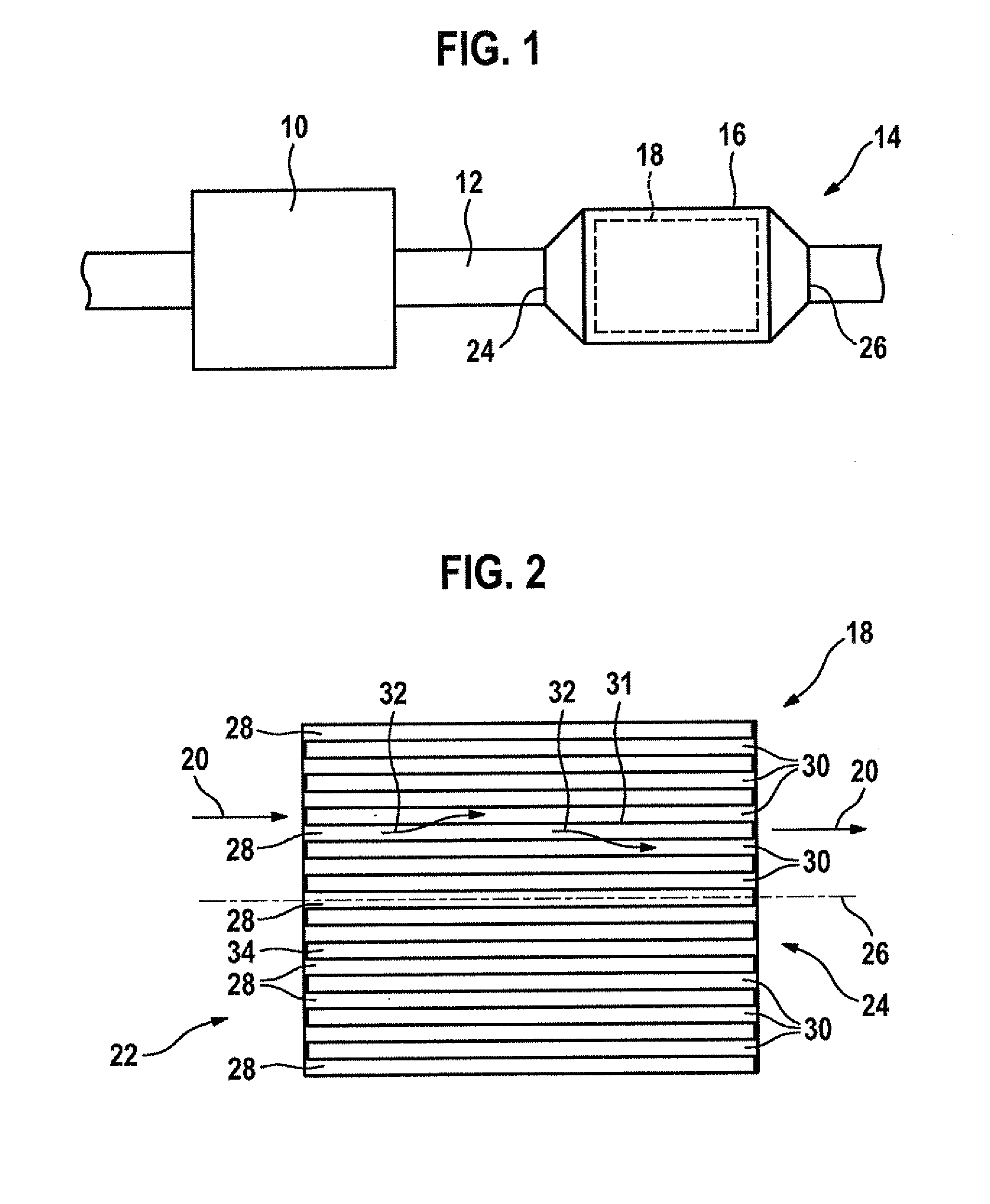
[0018]FIG. 1 shows a schematic diagram of an internal combustion engine having an exhaust gas aftertreatment device according to an example embodiment of the present invention.

[0019]FIG. 2 shows a filter element according to an example embodiment of the present invention in a longitudinal section.

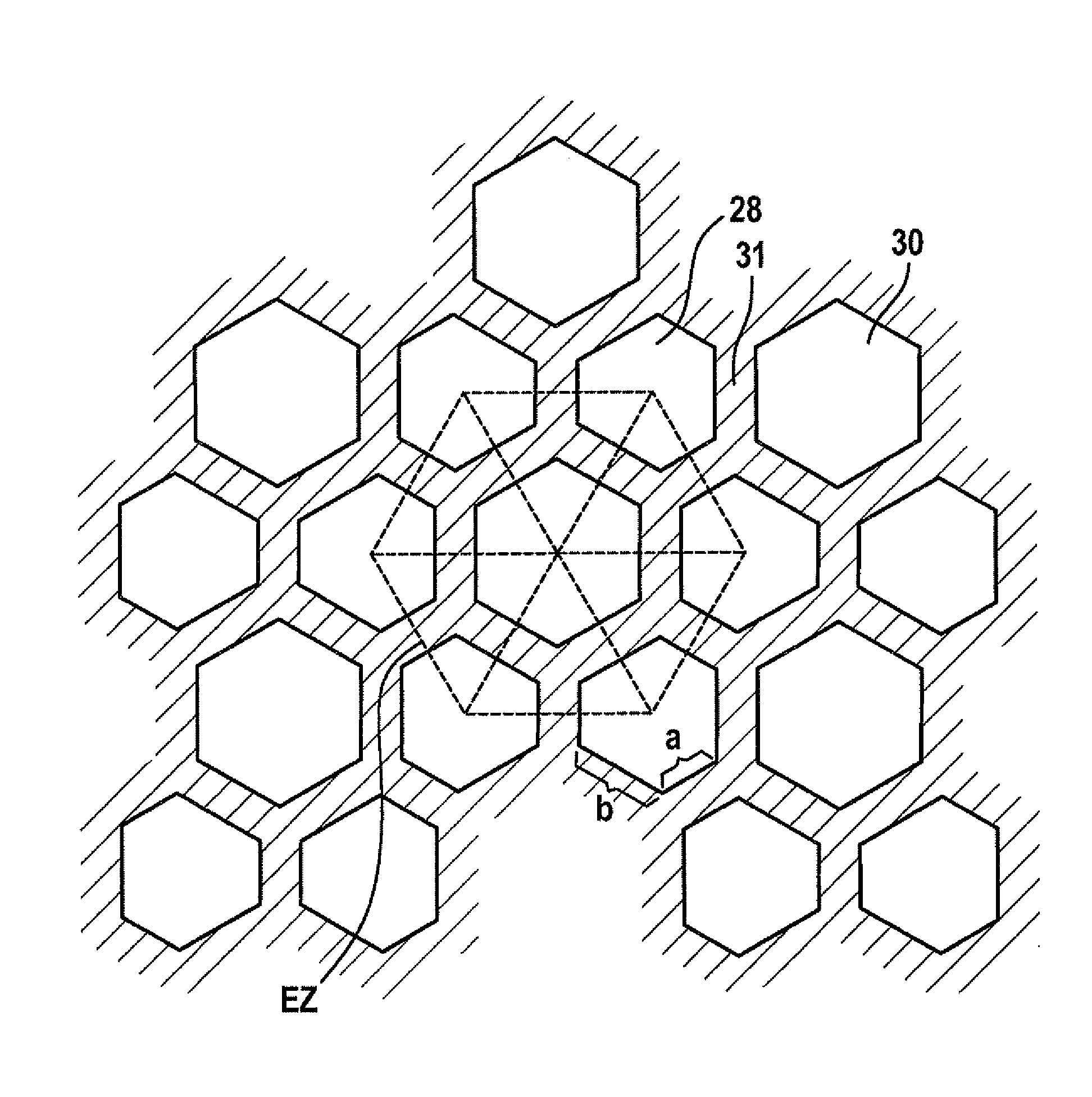
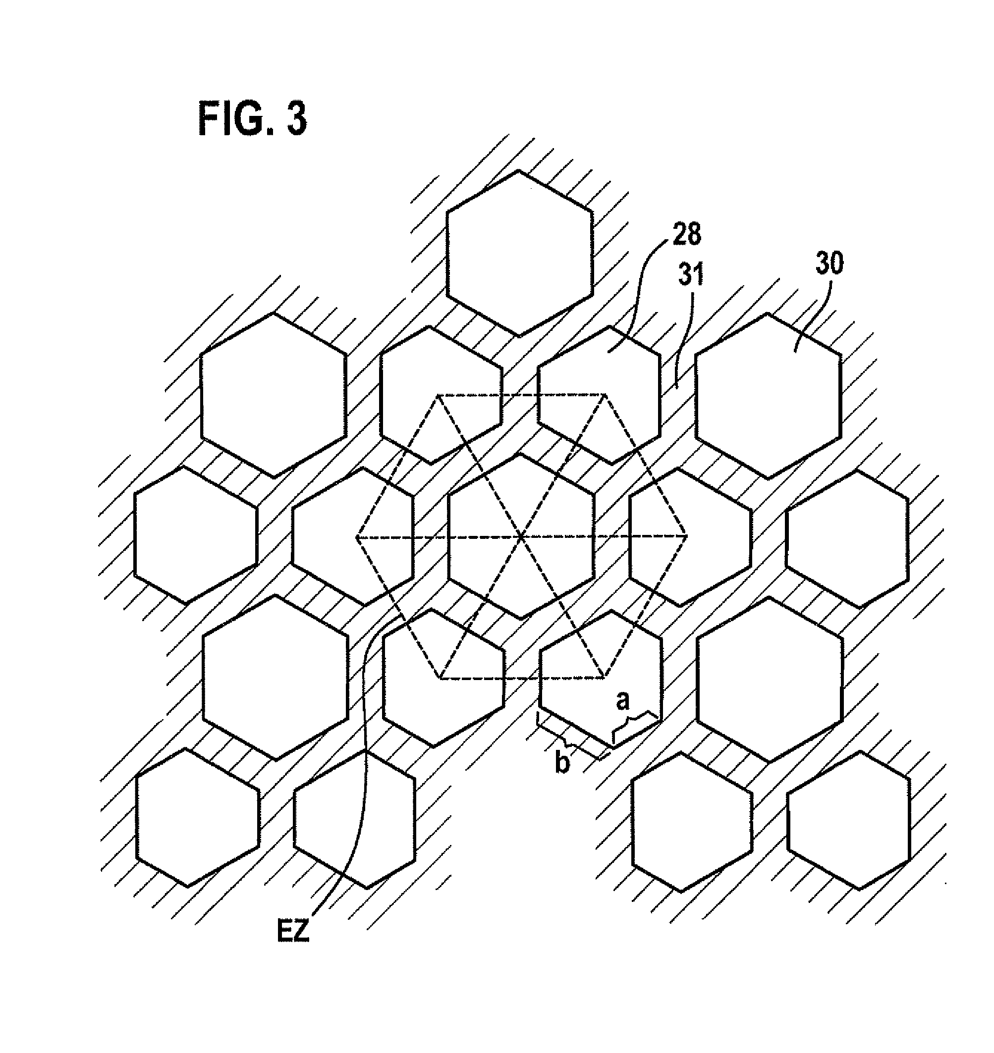
[0020]FIGS. 3 through 6 show cross sections of exemplary embodiments of filter elements according to the present invention.

DETAILED DESCRIPTION OF EXAMPLE EMBODIMENTS

[0021]FIG. 1 shows an internal combustion engine labeled with reference numeral 10. The exhaust gas is removed through an exhaust pipe 12 in which a filter device 14 is situated. Soot particles from the exhaust flowing through exhaust pipe 12 are filtered out with this filter device. This may be required in particular for diesel internal combustion engines to meet statutory requirements.

[0022]Filter device 14 includes a cylindrical housing 16 in which a filter element 18 is situated, being rotationally symmetrical and also cyli...


PUM

PropertyMeasurementUnit
angleaaaaaaaaaa
thicknessaaaaaaaaaa
wall thicknessaaaaaaaaaa

Abstract

Cross-sectional geometries of filter elements for soot particle filters are described, allowing uniform loading of the filter element with soot. Starting with hexagonal cell shapes, other polygonal shapes are arranged around them. All the cross-sectional geometries have in common the fact that the cross-sectional area of all inlet channels is larger than the cross-sectional area of all outlet channels.

Description

FIELD OF THE INVENTION[0001]The present invention relates to a filter element, in particular for an exhaust system of an internal combustion engine, as well as a soot filter having a filter element.BACKGROUND INFORMATION[0002]European Patent No. EP 1 502 640 A1 describes a filter element having an inlet area and an outlet area, and a plurality of inlet channels and a plurality of outlet channels, the inlet channels having a hexagonal cross section and the outlet channels having a square or rhomboid cross section, and the inlet channels and outlet channels being separated by a filter wall made of an open-pored material.[0003]Filter elements are often made of a ceramic material and are usually manufactured by extrusion. This means that the filter element blank is a prismatic body having a plurality of channels running in parallel. The channels of a blank are initially open at both ends.[0004]To allow the exhaust gas that is to be cleaned to flow through the walls of the filter, some o...

Claims


Application Information

Patent Timeline
Patent Type & Authority Applications(United States)
IPC IPC(8): F01N3/022C04B38/00B01D46/24
CPCY02T10/20F01N3/0222Y02T10/12
Inventor KOMORI, TERUOSCHILLER, CHRISTIANTHUENER, LARSHUELSMEIER, DOMINIKHOEFFKEN, TOBIAS
Owner ROBERT BOSCH GMBH
Why Eureka
Try Eureka