Electrolysis installation

a technology of electrolysis and installation, which is applied in the direction of electrodes, diaphragms, photographic processes, etc., can solve the problems of reducing the resistance of separation membranes, and reducing the efficiency of electrolysis installation

Inactive Publication Date: 2009-08-20
SNECMA PROPULSION SOLIDE
View PDF7 Cites 4 Cited by
  • Summary
  • Abstract
  • Description
  • Claims
  • Application Information

AI Technical Summary

Benefits of technology

[0007]An object of the present invention is to remedy the above-mentioned drawbacks by proposing novel designs of electrolysis installations including separation membranes that enable the electrodes constituting the anode and cathode zones to be moved closer together and that withstand the above-mentioned corrosion-erosion phenomenon effectively.
[0009]Thus, with the separation membrane of the invention, it is possible to reduce the distance between the adjacent cathodes and anodes in the electrolysis installation and consequently to optimize the Faraday efficiency, even in the presence of corrosive gaseous species being given off. Since ions have dimensions that are much smaller than bubbles of gas, the membrane in the installation of the invention presents permeability that allows ions to pass through (a condition that is necessary for the electrolysis reaction to take place), but without also passing bubbles of the gaseous species given off on either side of the membrane. By reducing the distance between each series of electrodes, it is also possible to have a larger number of rows of electrodes in a given volume of vessel and thereby increase the productivity of the installation.
[0010]The membrane is made of a carbon / carbon material since that material withstands the corrosion-erosion phenomenon particularly well. Consequently, the membrane of the invention presents a long lifetime, thus ensuring great reliability in its function of keeping the gaseous species separate.
[0011]The membrane of the installation of the invention may be made solely of carbon / carbon material without modification, i.e. it need not be coated. In a variant embodiment, the surface of one or both faces of the membrane may be modified by treatment or coated with one or more particular materials, e.g. for the purposes of improving or reducing wetting or of conferring particular electrical properties.
[0012]In addition, by using fine fiber reinforcement that is densified by a carbon matrix, a membrane is obtained that is of small thickness while nevertheless being stiff. The membrane may also present an architecture of a particular shape, for example it may present a corrugated shape, thereby making it possible to further increase its stiffness.

Problems solved by technology

Nevertheless, such spacing between the anodes and the cathodes reduces the efficiency of the electrolysis installation.
When producing fluorine by electrolysis, as described above, the bubbles of gaseous fluorine that are given off give rise to corrosion and to erosion of the elements of the installation with which they come into contact during electrolysis.
The materials presently used for making separation membranes do not enable sufficient resistance to the corrosion-erosion phenomenon to be obtained and, by degrading prematurely, they run the risk of becoming permeable to the gaseous species that are given off.
One solution for providing better resistance would be to increase membrane thickness, but that would be equivalent to increasing the distance between the cathodes and the anodes, and would consequently reduce the Faraday efficiency and the productivity of the installation.

Method used


Image

  • Electrolysis installation
  • Electrolysis installation
  • Electrolysis installation

Examples


Embodiment Construction

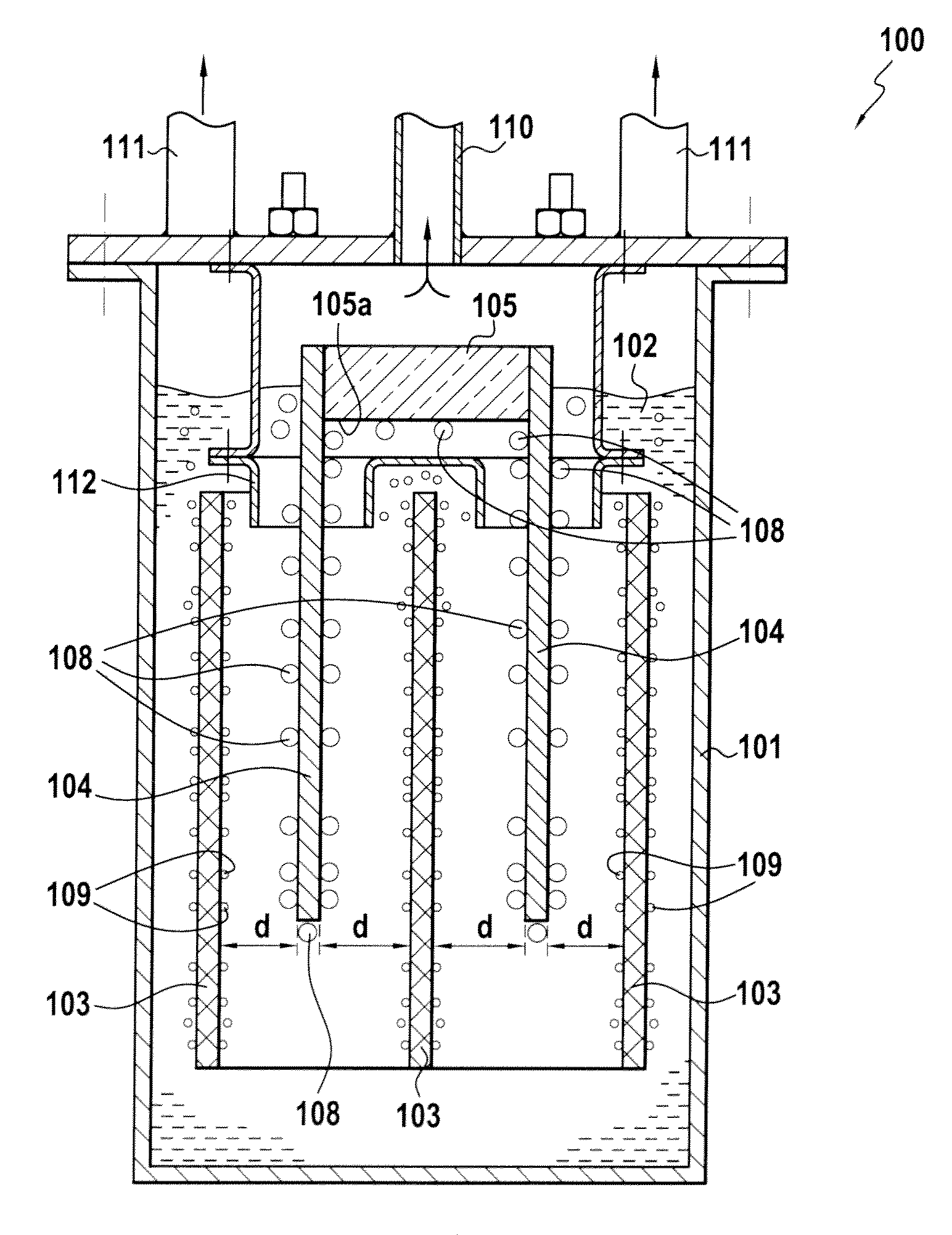
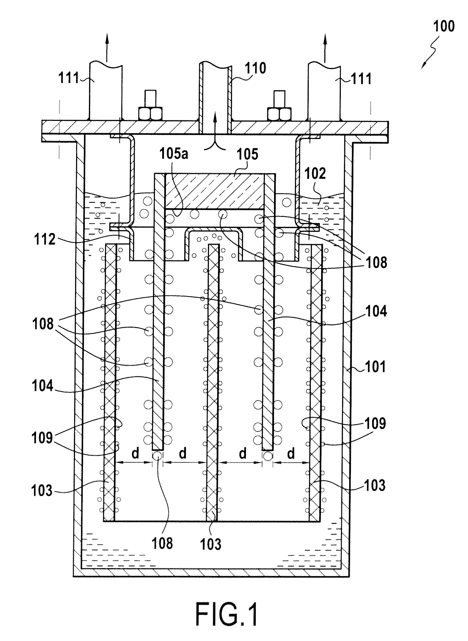
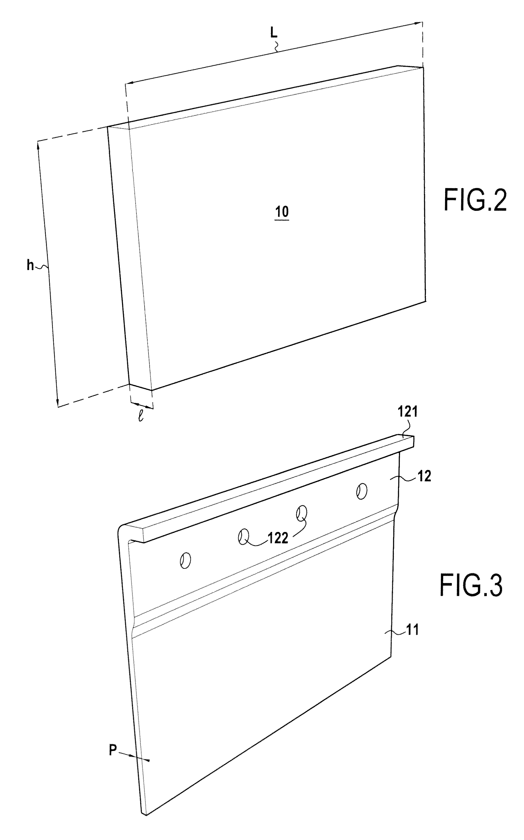
[0035]A particular but non-exclusive field of application for the invention is that of electrolysis installations for use in producing gaseous species of a corrosive nature such as fluorine or chlorine, for example. The present invention proposes reducing the distance between the cathodes and the anodes in such installations in order to increase their production efficiency. For this purpose, the present invention proposes interposing a separation membrane between two adjacent series of electrodes (cathodes and anodes), the membrane being constituted by a fine stiff plate of carbon / carbon (C / C) composite material that presents permeability to ions but that remains impermeable relative to the bubbles of gas given off at each electrode. The membrane of C / C material may be used as such, i.e. without surface coating or treatment, or on the contrary it may be coated or treated on one or both of its faces, e.g. for the purposes of improving or reducing its wettability or of giving it parti...


PUM

PropertyMeasurementUnit
thicknessaaaaaaaaaa
widthaaaaaaaaaa
angleaaaaaaaaaa

Abstract

The invention relates to an electrolysis installation comprising at least two rows of electrodes that are immersed at least in part in a liquid electrolyte giving off one or more gaseous species of corrosive nature at the electrodes, at least one separation membrane being disposed between two adjacent rows of electrodes. Each membrane is constituted by carbon fiber reinforcement stiffened by a carbon matrix and presents porous portion that is permeable to ions and impermeable to the or each gaseous species, given off at the electrolytes.

Description

BACKGROUND OF THE INVENTION[0001]The present invention relates to the field of electrolysis cells or installations. FIG. 1 is a diagram showing an electrolysis cells or installation 100 used for producing fluorine. The installation 100 comprises a vessel 101 containing an electrolyte 102, e.g. a solution of hydrofluoric acid (HF), and having immersed therein electrodes of two types, namely cathodes 103 and anodes 104. The anodes 104 are fastened and electrically connected to opposite sides of a busbar 105. The busbar 105 simultaneously provides support and delivers electrolysis current for the anodes 104. In well-known manner, the busbar 105 is connected to the positive terminal of a direct current (DC) generator (not shown in the figure), while the cathodes 103 are connected to the negative terminal of the generator. The anodes 104 are distributed longitudinally on either side of the busbar 105 and project beyond the bottom face 105a of the busbar.[0002]FIG. 1 shows the electrolysi...

Claims


Application Information

Patent Timeline
Patent Type & Authority Applications(United States)
IPC IPC(8): C25B9/08C25B11/00C25B9/17C25B9/19
CPCC25B1/245Y02E60/366C25B13/04C25B13/02C25B1/24Y02E60/36
Inventor MAUMUS, JEAN-PIERREDUMONT, CHARLESABBE, FRANCOIS
Owner SNECMA PROPULSION SOLIDE
Why Eureka
Try Eureka