Electrophotographic photoreceptor, image-forming apparatus, and electrophotographic cartridge

a photoreceptor and image-forming technology, applied in the direction of electrographic process, instruments, corona discharge, etc., can solve the problems of photosensitive layer surface wear, mechanical damage of the photoreceptor, and various defects in the image formed with the photoreceptor, etc., to achieve high sensitivity

Active Publication Date: 2009-08-20
MITSUBISHI CHEM CORP
View PDF15 Cites 17 Cited by
  • Summary
  • Abstract
  • Description
  • Claims
  • Application Information

AI Technical Summary

Benefits of technology

[0048]The present invention can provide an electrophotographic photoreceptor having a high sensitivity and being hardly affected by the ...

Problems solved by technology

In the organic photoreceptor, changes in use environment of the photoreceptor or changes in electric characteristics during repeated use may cause various defects in an image formed with the photoreceptor.
In this occasion, since the photoreceptor is repeatedly used, it undergoes various stresses causing deterioration.
In addition, the photoreceptor undergoes mechanical damage, e.g., wear of the photosensitive layer surface, scratching, and delamination, which are caused by friction with a charging roller or a charging brush, which are in...

Method used


Image

  • Electrophotographic photoreceptor, image-forming apparatus, and electrophotographic cartridge
  • Electrophotographic photoreceptor, image-forming apparatus, and electrophotographic cartridge
  • Electrophotographic photoreceptor, image-forming apparatus, and electrophotographic cartridge

Examples


first embodiment

of Preferable Dispersion Apparatus

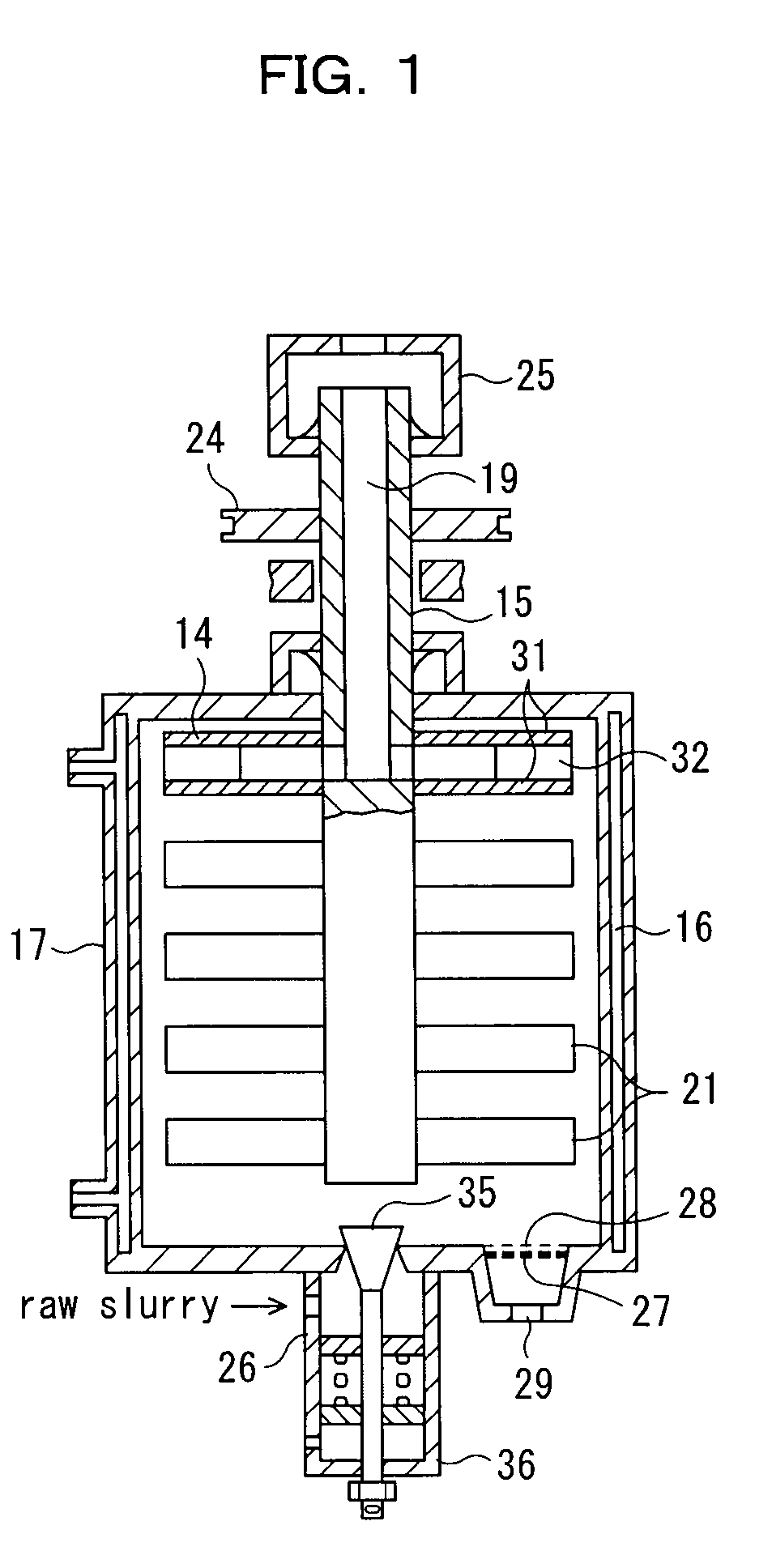
[0293]Among the aforementioned wet agitating ball mills, particularly preferred is one including a cylindrical stator, a slurry supplying port disposed at one end of the stator, a slurry discharging port disposed at the other end of the stator, a rotor for agitating and mixing a dispersion medium packed in the stator and slurry supplied from the supplying port, and a separator that is rotatably connected to the discharging port and separates the dispersion medium and the slurry by the centrifugal force to discharge the slurry from the discharging port.

[0294]Here, the slurry contains at least metal oxide particles and a dispersion solvent.

[0295]Now, the structure of this wet agitating ball mill will now be described in detail.

[0296]The stator is a tubular (usually, cylindrical) container having a hollow portion and is provided with a slurry supplying port at one end and a slurry discharging port at the other end. In addition, the hollow portion of th...

second embodiment

of Preferable Dispersion Apparatus

[0325]Wet agitating ball mills other than the above-described wet agitating ball mill can be used in the dispersion step. For example, in order to ensure the separation of a dispersion medium from dispersion slurry, a wet agitating mill by a screen separation system is superior to that by a gap, slit, or centrifugation system. A wet agitating mill by the screen separation system has a screen for separating a medium, and slurry and a dispersion medium are separated by filtration through this screen. The wet agitating mill by the screen separation system has an advantage in that it can constantly separate metal oxide particles having a particle diameter distribution according to the present invention from a dispersion medium. In particular, in the case of use of a fine dispersion medium with a 5 to 100 μm diameter, the separation of the dispersion medium by a wet agitating mill of the gap system or the slit system is practically very difficult. Furthe...

examples

[0744]The present invention will now be described in further detail with reference to Examples and Comparative Examples, but is not limited thereto within the scope of the present invention. In the description of Examples, the term “part(s)” means “part(s) by weight” unless otherwise specified, and the term “%” means “mass %” unless otherwise specified. In the description of Examples, the term “Me” denotes a methyl group.


PUM

PropertyMeasurementUnit
Lengthaaaaaaaaaa
Lengthaaaaaaaaaa
Fractionaaaaaaaaaa

Abstract

An electrophotographic photoreceptor having high sensitivity and hardly affected by the transfer in an electrophotographic process is provided. The electrophotographic photoreceptor includes an undercoat layer containing metal oxide particles and a binder resin and a photosensitive layer disposed on the undercoat layer, wherein the metal oxide particles have a volume average particle diameter of 0.1 μm or less and a 90% cumulative particle diameter of 0.3 μm or less which are measured by a dynamic light-scattering method in a liquid of the undercoat layer dispersed in a solvent mixture of methanol and 1-propanol at a weight ratio of 7:3, and the photosensitive layer contains a binder resin having an ester bond.

Description

TECHNICAL FIELD[0001]The present invention relates to an electrophotographic photoreceptor having an undercoat layer, an image-forming apparatus and an electrophotographic cartridge that employ the photoreceptor.BACKGROUND ART[0002]Electrophotographic technology has been widely applied to the field of printers, as well as the field of copiers, due to its immediacy and formation of high-quality images. Electrophotographic photoreceptors (hereinafter, optionally, referred to as “photoreceptor”) lie in the core technology of electrophotography, and organic photoreceptors using organic photoconductive materials have been developed, since they have advantages such as non-pollution and ease in production in comparison with inorganic photoconductive materials.[0003]In general, an organic photoreceptor is composed of an electroconductive support and a photosensitive layer disposed thereon. Photoreceptors are classified into a so-called single-layer photoreceptor having a single photosensiti...

Claims


Application Information

Patent Timeline
IPC IPC(8): G03G15/00G03G15/04
CPCG03G5/056G03G5/0564G03G5/144G03G5/0616G03G5/0614G03G5/061473G03G5/061443G03G5/06149G03G5/061446
Inventor MITSUMORI, TERUYUKIISHIO, KOZOFUCHIGAMI, HIROETAKAMURA, HIROAKIKAWAI, YASUNORI
Owner MITSUBISHI CHEM CORP
Why Eureka
Try Eureka