High solid thermophilic anaerobic digester

a thermophilic anaerobic and digester technology, applied in biochemistry equipment, biochemistry apparatus and processes, water/sludge/sewage treatment, etc., can solve the problems of uneconomic use of scrubbed methane for heating raw sludge, economic unattractiveness of thermophilic digestion, etc., to reduce the size of sludge, and reduce the effect of sludge siz

Inactive Publication Date: 2009-08-20
IUT GLOBAL PTE
View PDF16 Cites 37 Cited by
  • Summary
  • Abstract
  • Description
  • Claims
  • Application Information

AI Technical Summary

Benefits of technology

[0014]A third aspect of the present invention is directed to a system for digesting sludge anaerobically. This system comprises screening means for removing inorganic material from raw sludge, shredding means for reducing the size of the raw sludge, and a device for digesting the raw sludge anaerobically in accordance with the present invention.
[0042]Prior to composting, it is possible to extract water from the digested sludge in order to recover and recycle the bacteria-rich water. So doing also enables the digested sludge to dry faster. In one embodiment, dewatering is carried out until the dry solid content in the fermented sludge is about 25% to about 30%. Dewatering is typically done by mechanically squeezing the digested sludge, for example in a screw press or any other equivalent equipment.

Problems solved by technology

However, anaerobic digestion typically requires long residence times to allow the anaerobic bacteria time to breakdown the organic material in the sludge (see U.S. Pat. No. 5,637,219).
For this reason, thermophilic digestion is often considered to be economically unattractive for the treatment of sludge because the heat source required to operate the digester is seldom justified by the economic benefit derived from the production of raw methane gas (which contains corrosive components) and compost.
The draft tubes provide control of the digestion process to accommodate the formation of scum and foam, which may be detrimental to mixing within the digester if not managed properly.
However, the use of scrubbed methane for heating the raw sludge is not economical, since operation of the scrubber is costly and the scrubbed methane can be sold.

Method used


Image

  • High solid thermophilic anaerobic digester
  • High solid thermophilic anaerobic digester
  • High solid thermophilic anaerobic digester

Examples


Embodiment Construction

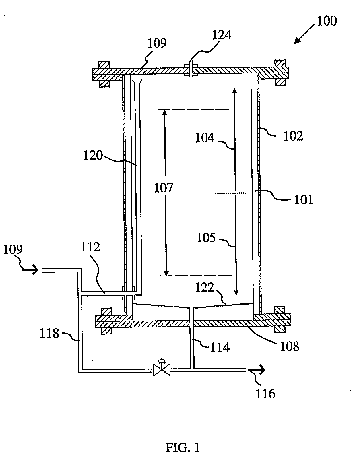
[0052]FIG. 1 shows a first embodiment of the device according to the invention. In this embodiment, the device 100 comprises a digesting tank 102 having an upper region as denoted by the arrow 104 and a lower region denoted by the arrow 105. Arranged within the digesting tank 102 is a reaction chamber 107 where anaerobic digestion of sludge takes place. A raw sludge stream 109 is introduced into the digester via inlet 112 located at the lower region 105 and leaves the digesting tank via outlet 114. A portion of the matured sludge is discharged via discharge stream 116 while the remaining portion of the matured sludge is recycled via recycle stream 118. Recycle stream 118 is combined with raw sludge stream 109 at inlet 112, thereby mixing mature sludge with raw sludge (hereinafter known as mixed sludge). This provides the raw sludge with the necessary anaerobic bacteria required for it to be digested. Mixed sludge enters the digesting tank 102 via the inlet 112. The inlet 112 is conn...


PUM

PropertyMeasurementUnit
diameteraaaaaaaaaa
temperatureaaaaaaaaaa
operating temperatureaaaaaaaaaa

Abstract

A device for digesting sludge anaerobically, comprising a digesting tank (100) having an upper region (104) and a lower region (105), and a reaction chamber (107) for converting raw sludge into matured sludge, an inlet (112) for introducing sludge (109) into the digesting tank, at least one transfer pipe (120) for channelling sludge from the lowe region of the digesting tank to the upper region of the digesting tank, said at least one transfer pipe being arranged within the digesting tank and having at least a part of its length thereof arranged within the reaction chamber so that least one transfer pipe is in contact with sludge moving through the reaction chamber, thereby resulting in heat transfer from sludge moving in at least on transfer pipe to sludge in the reaction chamber, and an outlet (114) arrange at the lower region of the digesting tank for discharging matured sludge (116) from the digesting tank.

Description

[0001]The present invention relates generally to the field of waste treatment, and more particularly to a device, a process and a system for the anaerobic digestion of organic sludge.BACKGROUND OF THE INVENTION[0002]Anaerobic digestion is a commonly used process for the treatment of organic waste material. Many types of organic wastes can be treated by anaerobic digestion, including agricultural, domestic and industrial wastes. One of the chief objectives in carrying out digestion of organic waste is to convert sludge solids into a clean effluent suitable for discharge into the environment. The production of methane, a combustible fuel, as a by-product of the anaerobic digestion process is also an important aspect of the operation of an anaerobic digestion plant which helps to lower the running costs of the plant. As organic waste is produced in large quantities from both industrial, commercial, and agricultural cities, the treatment of organic wastes via anaerobic digestion represe...

Claims


Application Information

Patent Timeline
Patent Type & Authority Applications(United States)
IPC IPC(8): A62D3/02C12M1/00
CPCC02F3/2873C02F11/04Y02E50/343C12M29/18C12M41/12C12M21/04Y02E50/30Y02W10/10Y02W10/20
Inventor GOSCHL, REINHARDKHEW, TECK FOOK EDWIN
Owner IUT GLOBAL PTE
Why Eureka
Try Eureka