Glazing

Active Publication Date: 2009-08-20
PILKINGTON GROUP LTD
View PDF1 Cites 3 Cited by
  • Summary
  • Abstract
  • Description
  • Claims
  • Application Information

AI Technical Summary

Benefits of technology

[0010]The present invention provides a method of modifying a glazing material by reducing its opacity to a signal so as to improve its suitability f

Problems solved by technology

These relatively opaque regions can interfere with or block completely the transmission of certai

Method used


Image

  • Glazing
  • Glazing
  • Glazing

Examples


Example

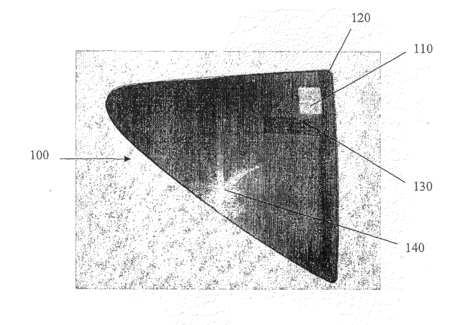
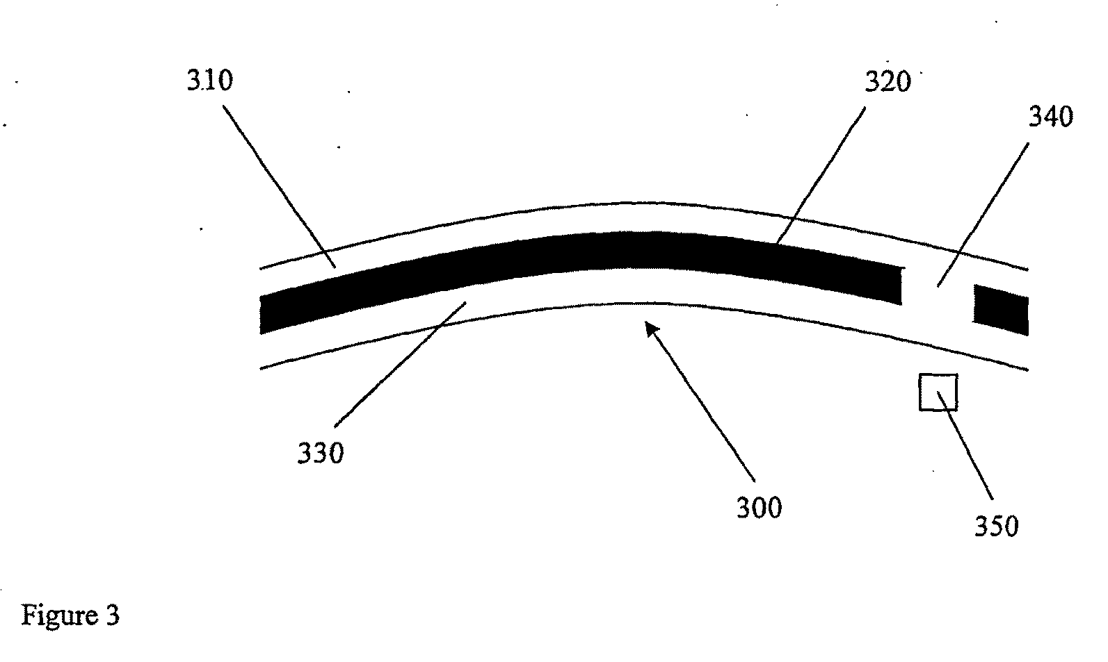
[0031]A glazing comprising a 0.76 mm charcoal grey PVB interlayer laminated between two outer pieces of 2.1 mm thick clear glass was used for initial testing.

[0032]Testing was performed using a solid state, pulsed laser. Such lasers are used in the removal of coatings from glass, such as described in US 2003 / 0075531, and typically operate at 532 nm with a nanosecond pulse time. The spot size, laser power level and pulse frequency are adjusted for the nature of the sample treated.

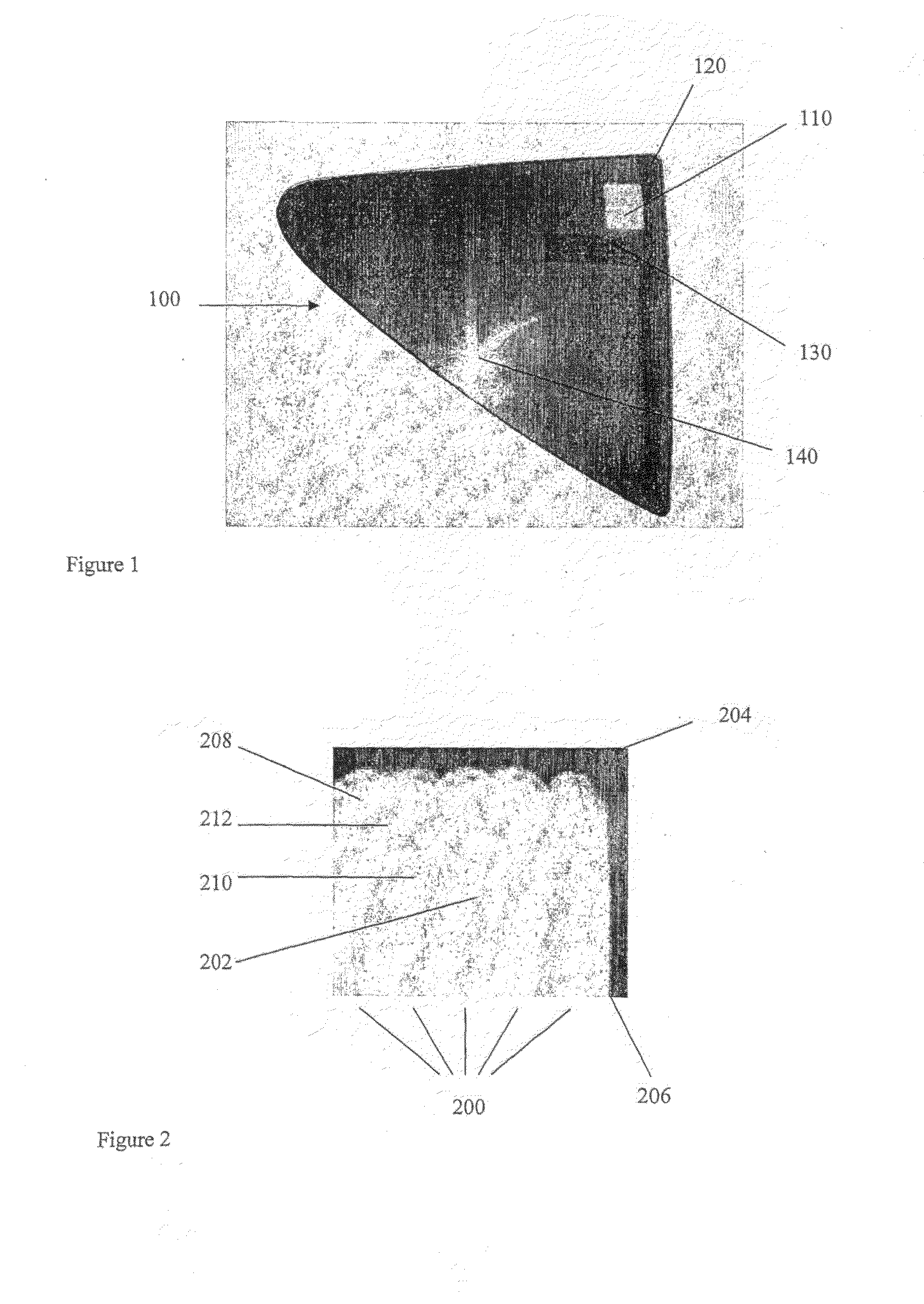
[0033]The sample was treated by scanning a region of the glazing with the laser beam. The laminated glazing may be held in a fixed position and the laser moved, the laser held in a fixed position and the glazing moved, or both moved, to achieve this scanning. The key point is that the laser is set up to move relative to the laminated glazing in a carefully controlled manner. Several parallel passes of the laser relative to the laminated glazing were made. This resulted in corresponding parallel tracks of the...


PUM

PropertyMeasurementUnit
Fractionaaaaaaaaaa
Fractionaaaaaaaaaa
Fractionaaaaaaaaaa

Abstract

A laser can be used to modify a glazing 100, 300 so as to improve its suitability for use with a signal-receiving device 350 or a signal-transmitting device 350. This is done by using the laser to provide a region of reduced opacity 110, 202, 340 to the signal within the glazing. Preferably, the laser is be used to reduce the opacity of a selected region 340 of a tinted interlayer in situ. The glazing may be for a vehicle, especially an automotive vehicle.

Description

TECHNICAL FIELD[0001]The present invention relates to a glazing and, in particular, to a glazing that is suitable for use with a signal-detecting or a signal-transmitting device.BACKGROUND ART[0002]Signal-detecting devices and signal-transmitting devices are well known and are nowadays used increasingly in combination with glazings. This is particularly the case for glazings used in sophisticated, high value products, such as glazings used in automotive vehicles. The devices are positioned on the glazing in the inside of the vehicle, to transmit or receive signals through the glazing.[0003]A signal-detecting device may, for example, be used to detect events or conditions occurring outside an automotive vehicle. The signal may, for example, be used to assess or detect changes in weather conditions (e.g. temperature, pressure, sunlight, rain, fog, mist, snow, ice), noise levels, vibration levels, sound levels, motion, etc. Typical sensors used in automotive vehicles include rain senso...

Claims


Application Information

Patent Timeline
IPC IPC(8): C08G2/26C08J3/28B32B17/10
CPCB32B17/10036B32B17/1099B32B17/10761B32B17/1066
Inventor LYON, MICHAELGREENALL, MICHAEL ROBERT
Owner PILKINGTON GROUP LTD
Why Eureka
Try Eureka