Devices, methods, and systems for harvesting energy in the body

a technology of energy harvesting and body, applied in the direction of generator/motor, machine/engine, therapy, etc., can solve the problem of high current drain of the battery

Inactive Publication Date: 2009-08-27
AUTONOMIC TECH INC
View PDF31 Cites 165 Cited by
  • Summary
  • Abstract
  • Description
  • Claims
  • Application Information

AI Technical Summary

Benefits of technology

[0033]In some embodiments, the first capacitance is less than the second capacitance, and in some embodiments, the capacitor has the second capacitance when the second plate contacts the insulator. In some embodiments, the first plate defines an aperture through which the dielectric fluid flows. In some embodiments, the dielectric constant of the insulator is higher than the dielectric constant of the dielectric fluid.

Problems solved by technology

Conventional spinal cord stimulators typically have either large batteries that are uncomfortable for the patient, or smaller batteries that require frequent recharging.
Additionally, for example, conventional Cardiac Resynchronization Therapy (CRT) Implantable Cardioverter Defibrillators (ICDS) stimulate the heart frequently and as a result have a high current drain from the battery and typically only last a few years before they need to be replaced due to battery depletion.

Method used


Image

  • Devices, methods, and systems for harvesting energy in the body
  • Devices, methods, and systems for harvesting energy in the body
  • Devices, methods, and systems for harvesting energy in the body

Examples


first embodiment

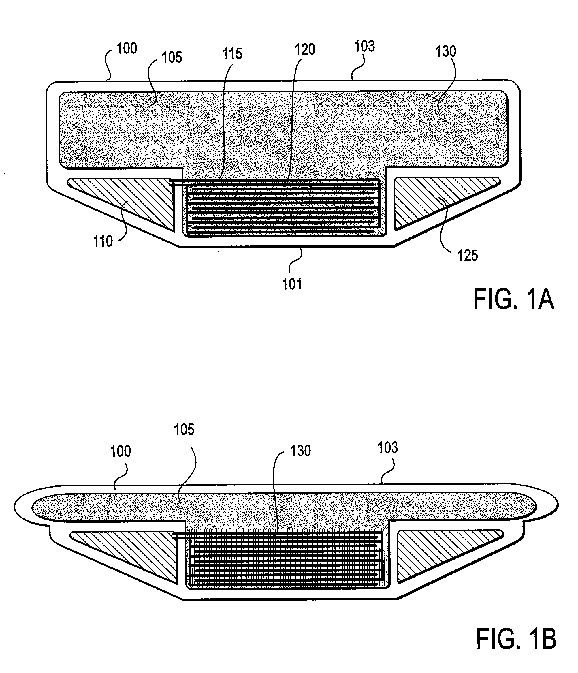
[0091]FIG. 1A shows a power generator of a The power generator as shown in FIG. 1A includes a housing 100 that defines a chamber 105. There is a capacitor 115 and a phase changing dielectric fluid 130 in the chamber. The capacitor has two plates having a space 120 between them that is in fluid communication with the fluid 130 in the rest of the chamber. The housing includes portion 103 that moves with respect to portion 101, such that, as shown in FIG. 1B, the housing is compressible. As the housing 100 is compressed, the volume of the fluid 130 is reduced, and the fluid changes phases. The capacitance of the capacitor changes as the phase changes, and electrical energy is generated in the form of the voltage and / or charge on plates of the capacitor, as the capacitance between these plates changes.

[0092]In the first embodiment, as shown in FIGS. 1A and 1B, the power generator for converting any suitable form of mechanical energy to electrical energy includes a housing 100 that defi...

second embodiment

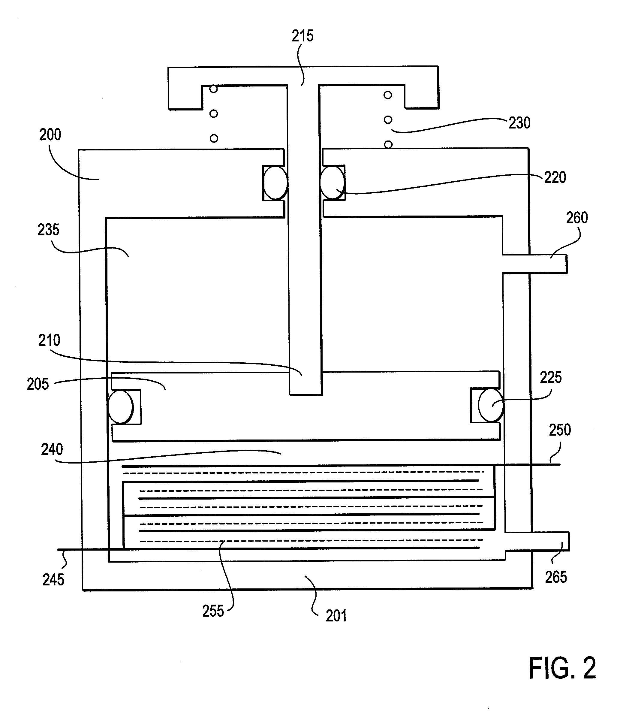
[0106]FIG. 2 shows a power generator of a The power generator as shown in FIG. 2 includes a housing 200 that defines a chamber. The chamber is divided into two portions 235 and 240 by the piston head 205. There is a capacitor and a phase changing dielectric fluid in chamber portion 240. The capacitor has two plates 245 and 250 having a space between them that is in fluid communication with the fluid in the rest of the chamber portion 240. The piston head 205 is coupled to a piston 210 and to a button 215 that move the piston head within the chamber toward the base 201 of the housing 200. As the piston head 205 moves toward the base 201, the volume of the fluid within the chamber portion 240 is reduced, and the fluid changes phases. The capacitance of the capacitor changes as the phase changes, and electrical energy is generated in the form of the voltage and / or charge on plates of the capacitor, as the capacitance between these plates changes.

[0107]In a second embodiment, the power...

third embodiment

[0111]FIG. 3A shows a power generator of a The power generator as shown in FIG. 3A includes a housing 300. The housing encloses a capacitor and a dielectric fluid. The capacitor has a first plate 310 and a second plate 320 coupled to the inside wall of the housing 300. The plate 310 is coupled to an insulator 315 and may define one or more apertures 305, which allow passage of the fluid through the plate 310. The housing includes portion 301 that, as force 355 is applied, moves with respect to a portion 302, such that, as shown in FIG. 3B, the housing is compressible. As the housing 300 is compressed, and as plate 320 moves toward plate 310 and / or insulator 315, the fluid is displaced from between the plates of the capacitor. The capacitance of the capacitor changes as the amount of dielectric fluid between the plates changes, and electrical energy is generated in the form of the voltage and / or charge on plates of the capacitor, as the capacitance between these plates changes.

[0112...


PUM


Abstract

In some embodiments, the power generator for converting mechanical energy to electrical energy is described may include a compressible element adapted and configured to be placed in an environment having a variable compressive force such as varying ambient pressures. The compressible element may be compressed by a force applied by the variable pressure to the compressible element. The power generator may further include a transducer that may be coupled to the compressible element and that may convert mechanical energy from the compression of the compressible element to electrical energy. In some embodiments, the power generator may be adapted to be an implantable power generator for converting mechanical energy from a patient to electrical energy, such that the compressible element adapted and configured to be placed between two adjacent tissue layers of the patient and to be compressed by a force applied from the two adjacent tissue layers to the compressible element.

Description

CROSS REFERENCE TO RELATED APPLICATIONS[0001]This application claims the benefit of priority of U.S. Provisional Patent Application Ser. No. 61 / 031,272 filed Feb. 25, 2008 titled “IMPLANTABLE POWER GENERATOR”; U.S. Provisional Patent Application Ser. No. 61 / 125,855 filed Apr. 26, 2008 titled “LIQUID CAPACITIVE ELECTRICAL GENERATOR”; U.S. Provisional Patent Application Ser. No. 61 / 081,261 filed Jul. 16, 2008 titled “ENERGY HARVESTING WITH DIELECTRIC PHASE CHANGE”; U.S. Provisional Patent Application Ser. No. 61 / 093,988 filed Sep. 3, 2008 titled “TRANSMISSION OF HARVESTED ENERGY IN THE BODY”; U.S. Provisional Patent Application Ser. No. 61 / 096,259 filed Sep. 11, 2008 titled “MEDICAL DEVICES UTILIZING IMPLANTABLE POWER GENERATOR”; and U.S. Provisional Patent Application Ser. No. 61 / 098,688 filed Sep. 19, 2008 titled “ELECTROMAGNETIC IMPLANTABLE ENERGY HARVESTER”; each of which are incorporated herein by reference in their entirety.INCORPORATION BY REFERENCE[0002]All publications and pa...

Claims


Application Information

Patent Timeline
Patent Type & Authority Applications(United States)
IPC IPC(8): A61N1/378H02K7/18H02N11/00H02N2/18
CPCA61N1/3785H02N11/002H02N2/18
Inventor PLESS, BENJAMIN DAVIDBOLING, CARL LANCEGIBB, BARBARAHEIDE, ADOLF VAN DERWINGEIER, BRETT M.
Owner AUTONOMIC TECH INC
Why Eureka
Try Eureka