Control device of internal combustion engine

a control device and internal combustion engine technology, applied in the direction of electrical control, process and machine control, instruments, etc., can solve the problems of catalyst melting damage, air-fuel ratio shift toward a lean side, excessive intake air quantity with respect, etc., and achieve the effect of improving control accuracy of intake air quantity during the restriction of intake air quantity

Inactive Publication Date: 2009-08-27
DENSO CORP
View PDF3 Cites 20 Cited by
  • Summary
  • Abstract
  • Description
  • Claims
  • Application Information

AI Technical Summary

Benefits of technology

[0018]Also with such the construction, the control accuracy of the intake ai

Problems solved by technology

Therefore, if the actual injection quantity is restricted with the maximum injection quantity that can be injected by the single normal injector, the intake air quantity becomes excessive with respect to the actual injection

Method used


Image

  • Control device of internal combustion engine
  • Control device of internal combustion engine
  • Control device of internal combustion engine

Examples


first embodiment

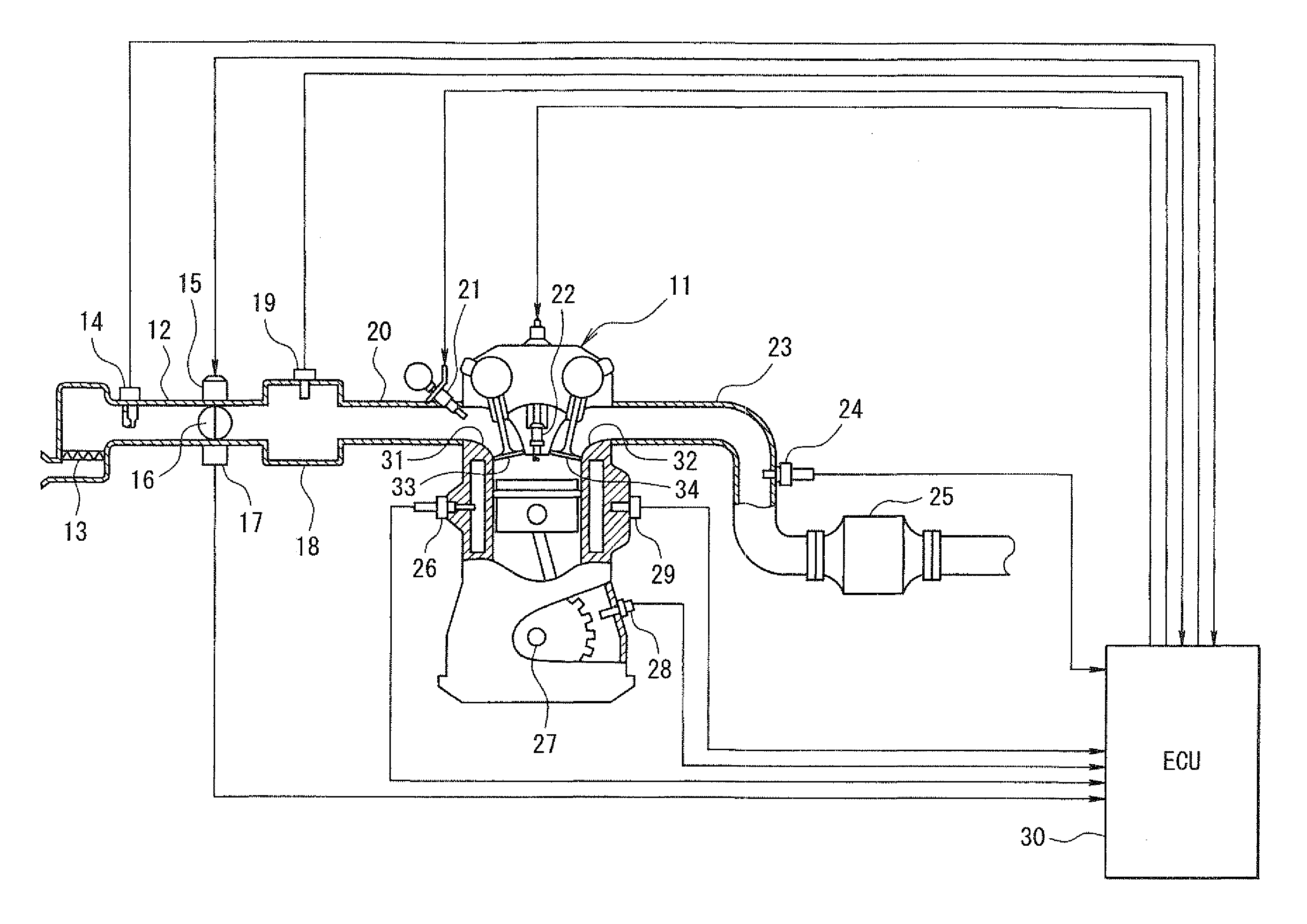
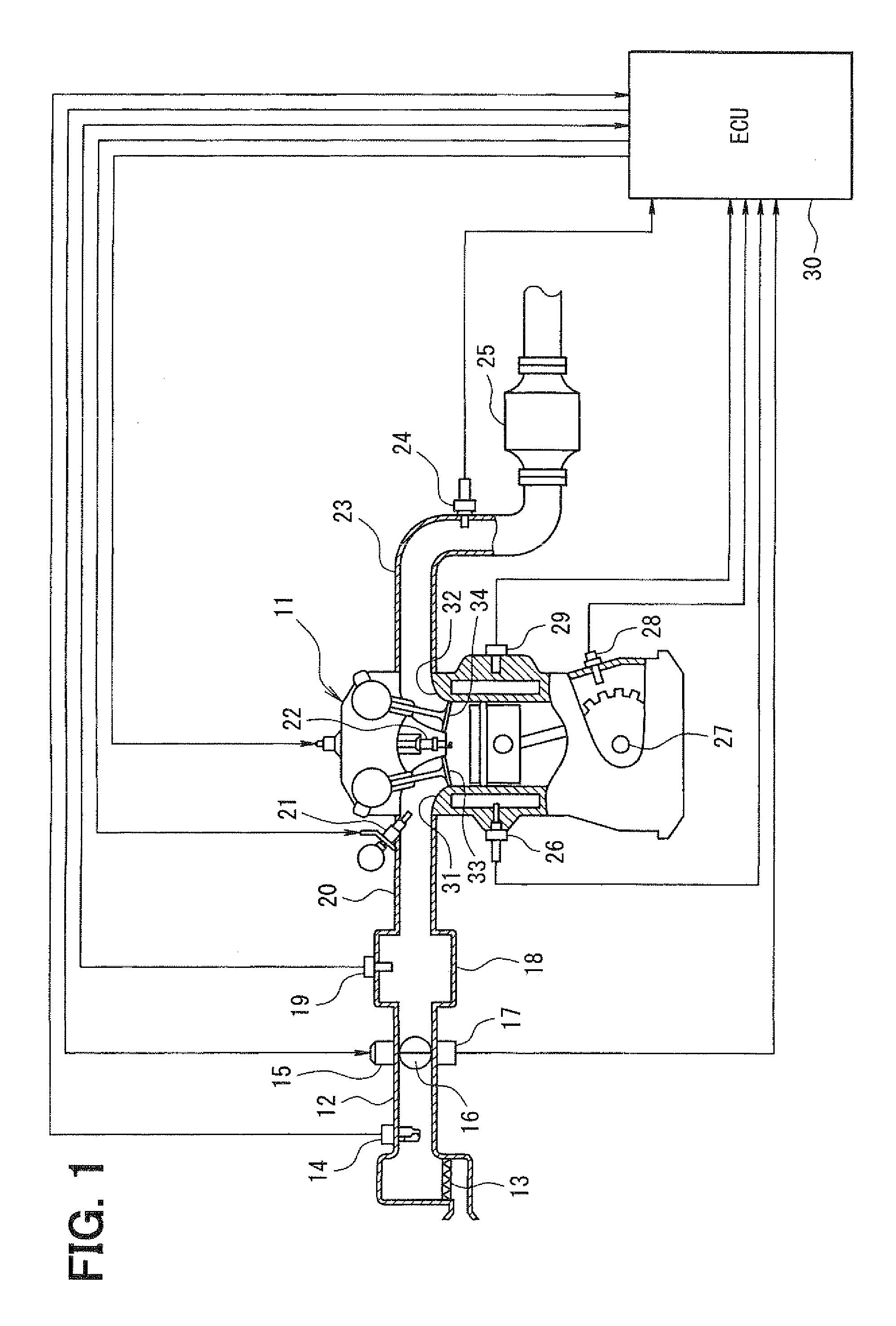
[0029]the present invention will be described with reference to FIGS. 1 to 4. First, a general configuration of an entire engine control system will be explained with reference to FIG. 1. An air cleaner 13 is provided in the most upstream portion of an intake pipe 12 of an engine 11 (an internal combustion engine). An airflow meter 14 for sensing intake air quantity is provided downstream of the air cleaner 13. A throttle valve 16, whose opening degree is regulated by a motor 15, and a throttle position sensor 17 for sensing an opening degree (a throttle opening degree) of the throttle valve 16 are provided downstream of the airflow meter 14.

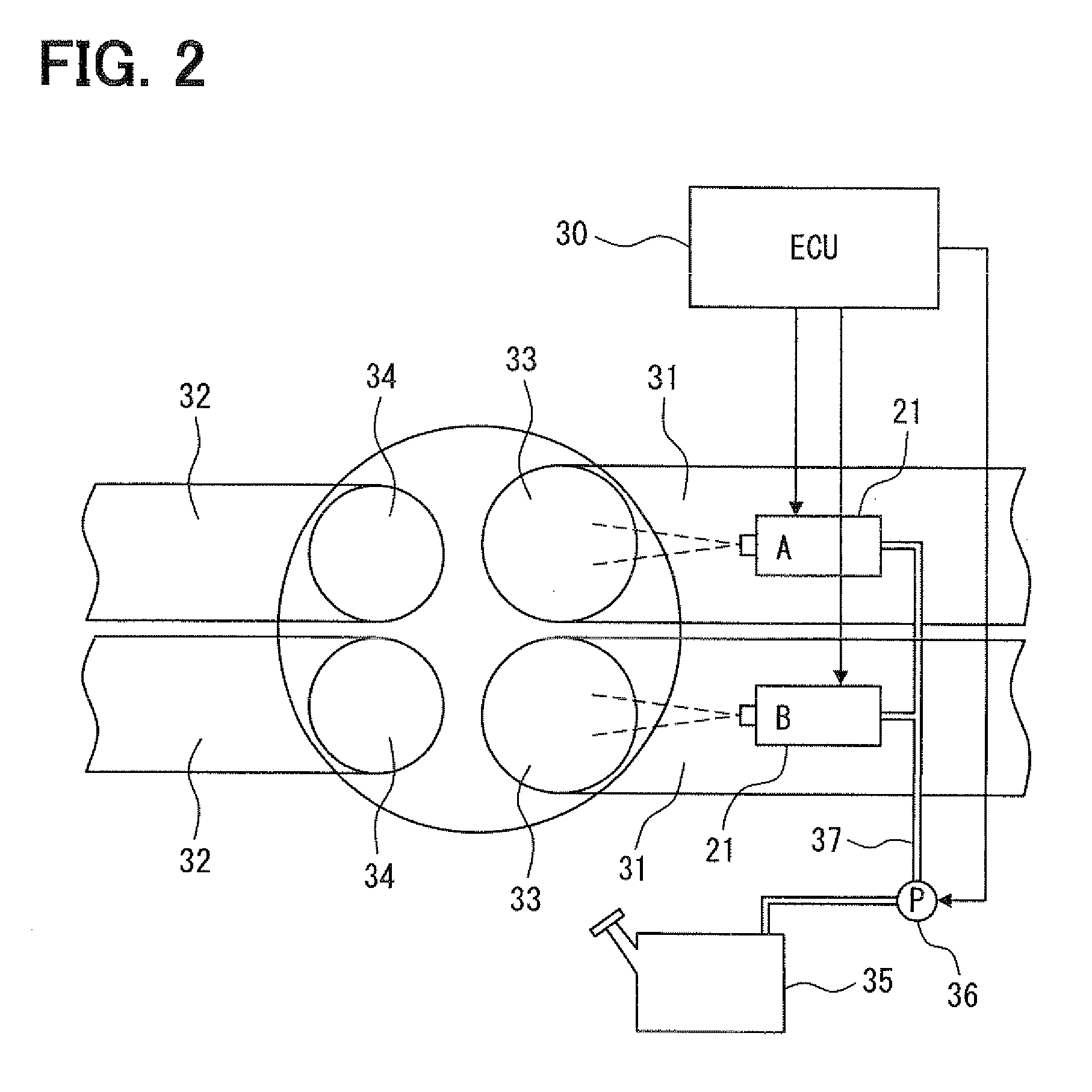
[0030]A surge tank 18 is provided downstream of the throttle valve 16, and an intake pipe pressure sensor 19 for sensing intake pipe pressure is provided to the surge tank 18. An intake manifold 20 for introducing an air into each cylinder of the engine 11 is provided to the surge tank 18. An injector 21 for injecting fuel is attached to or near...


PUM


Abstract

When either one of two injectors of each cylinder becomes abnormal, a control device performs failsafe control of performing increase correction of injection quantity of a normal injector. If actual injection quantity is restricted with the maximum injection quantity that can be injected by the normal injector during the execution of the failsafe control, the control device restricts duty of an actuator of an intake air quantity adjustment mechanism (such as a throttle opening degree), thereby restricting intake air quantity to intake air quantity that does not cause melting damage of a catalyst. Thus, increase of deviation of an air-fuel ratio toward a lean side can be inhibited, and the melting damage of the catalyst can be prevented.

Description

CROSS REFERENCE TO RELATED APPLICATION[0001]This application is based on and incorporates herein by reference Japanese Patent Application No. 2008-46935 filed on Feb. 27, 2008.BACKGROUND OF THE INVENTION[0002]1. Field of the Invention[0003]The present invention relates to a control device of an internal combustion engine having multiple injectors on an intake side of each of cylinders of the internal combustion engine respectively.[0004]2. Description of Related Art[0005]Patent document 1 (JP-A-S63-94057) describes a system that provides two injectors on an intake side of each cylinder of an internal combustion engine and that injects fuel into each cylinder by the two injectors, aiming at atomization of a fuel spray inside each cylinder of the internal combustion engine, reduction of port wetting (i.e., reduction of fuel adhesion to an intake port inner wall surface), and the like.[0006]The inventors of the present invention are studying an abnormality diagnosis technology for spec...

Claims


Application Information

Patent Timeline
IPC IPC(8): F02D41/30
CPCF02B31/085Y02T10/18F02D13/0261F02D41/0002F02D41/0055F02D41/1498F02D41/18F02D41/221F02D41/3094F02D41/34F02D2041/001F02D2200/0406F02M25/0752Y02T10/44Y02T10/42F02D13/0226F02M26/01Y02T10/12Y02T10/40
Inventor YAMASHITA, HIROSHIANNOURA, TOSHIKI
Owner DENSO CORP
Why Eureka
Try Eureka