
Layer-structured fuel cell catalysts and current collectors

a catalyst layer and catalyst technology, applied in the field of fuel cells, can solve the problems of fuel cell activation loss, fuel cell three major losses, and detrimental reduction of operating temperature, and achieve the effect of improving the adhesion of the catalyst layer

Inactive Publication Date: 2009-09-03
HONDA MOTOR CO LTD +1
View PDF5 Cites 33 Cited by
  • Summary
  • Abstract
  • Description
  • Claims
  • Application Information

AI Technical Summary

Benefits of technology

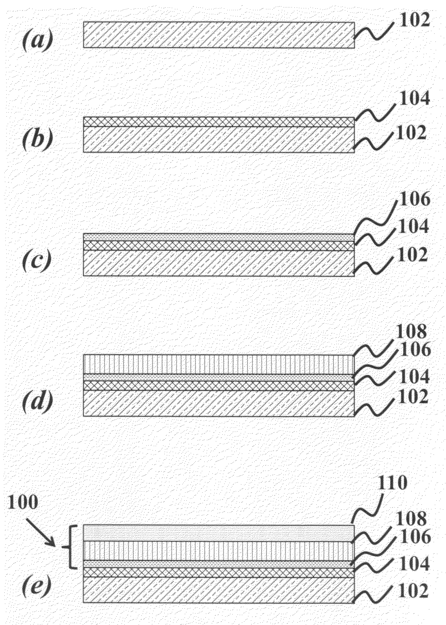
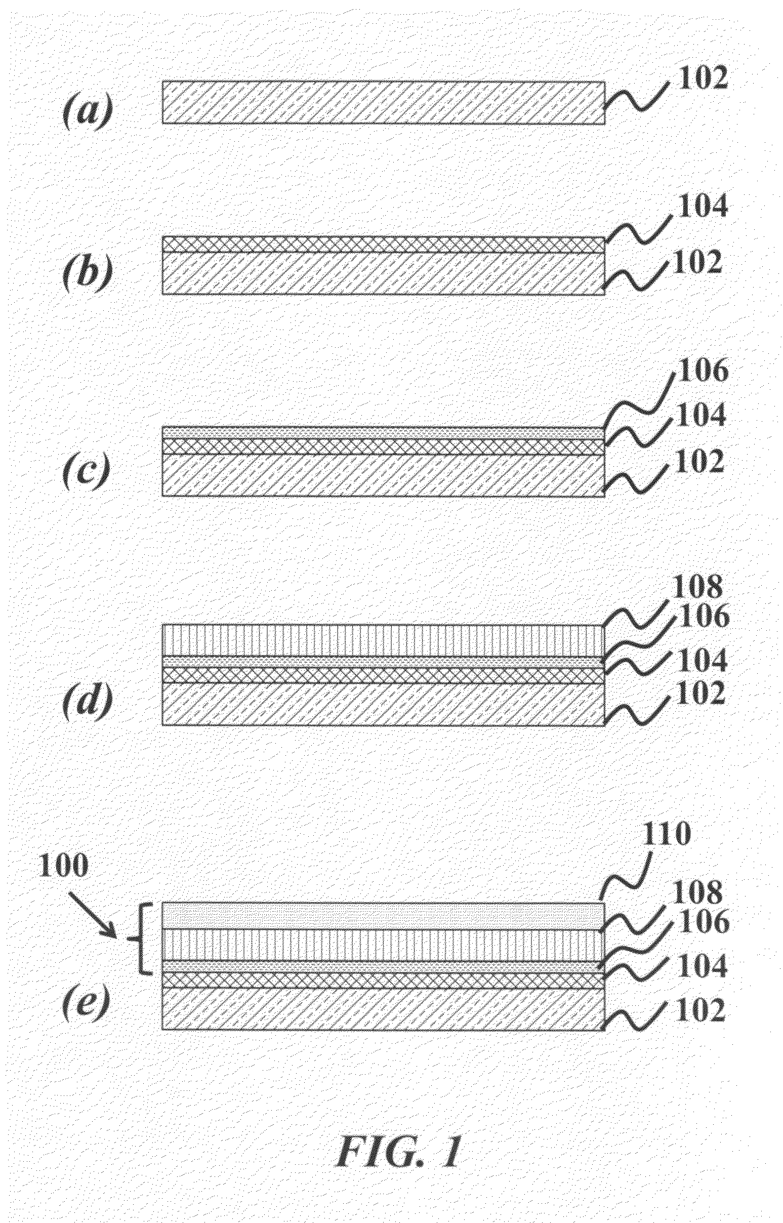
[0008]In order to address the current needs in the art, a method of fabricating layer-structured catalysts at the electrode / electrolyte interface of a fuel cell is provided. The method includes providing a substrate, depositing an electrolyte layer on the substrate, depositing a catalyst bonding layer to the electrolyte layer, depositing a catalyst layer to the catalyst bonding layer, where the catalyst bonding layer improves the adhesion of the catalyst layer onto the electrolyte layer and depositing a microstructure stabilizing layer to the catalyst layer.

Problems solved by technology

However, a reduction of the operating temperature is detrimental from an electrochemical point of view.
In general, fuel cells suffer from three major losses including (a) activation losses arising from sluggish kinetics of the electrochemical charge-transfer reactions at the electrodes, (b) ohmic loss mainly stemming from slow ionic conduction in the electrolyte, and (c) concentration loss originating from the limited mass transport at high current densities.
At reduced operating temperature, the thermally-activated electrode reactions and ion transport in the electrolyte become slower, resulting in lowered fuel cell performance.
Meanwhile, sufficient electrical connectivity is required, putting severe limitations on Pt film thickness by traditional deposition methods.
Though Pt provides excellent catalytic activity for the O2 reduction reaction and the H2 oxidation reaction at the electrode / electrolyte interface of an SOFC at low operating temperatures, pure Pt catalysts suffer from an increase of grain size and a decrease of porosity during fuel cell operation originating from the change of microstructure at high temperature.

Method used


Image

  • Layer-structured fuel cell catalysts and current collectors
  • Layer-structured fuel cell catalysts and current collectors
  • Layer-structured fuel cell catalysts and current collectors

Examples


Embodiment Construction

[0030]Although the following detailed description contains many specifics for the purposes of illustration, anyone of ordinary skill in the art will readily appreciate that many variations and alterations to the following exemplary details are within the scope of the invention. Accordingly, the following preferred embodiment of the invention is set forth without any loss of generality to, and without imposing limitations upon, the claimed invention.

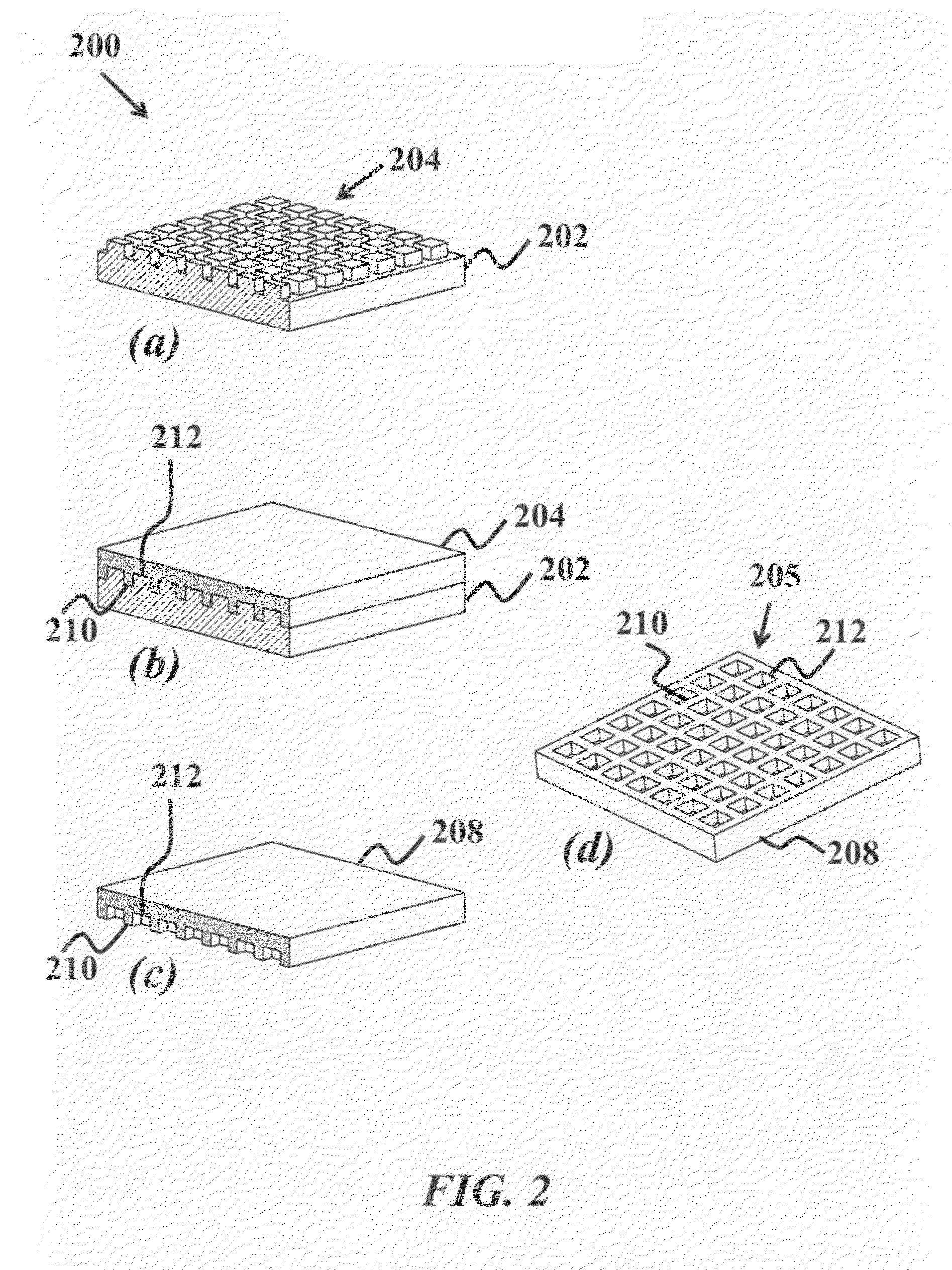
[0031]This present invention describes a method of fabricating a thermally stable, porous catalyst consisting of a layered-structure with precise control over the two-dimensional geometry and thickness, as well as fabricating a current collector with similar control. In one embodiment, the fabrication process employs atomic layer deposition (ALD) together with the patterning of a self-assembled monolayer (SAM) of polymers to selectively inhibit deposition. The current invention maintains catalytic activity while minimizing the loading of ...


PUM

PropertyMeasurementUnit
Currentaaaaaaaaaa
Catalytic activityaaaaaaaaaa
Microstructureaaaaaaaaaa

Abstract

A method of fabricating a layer-structured catalysts at the electrode / electrolyte interface of a fuel cell is provided. The method includes providing a substrate, depositing an electrolyte layer on the substrate, depositing a catalyst bonding layer to the electrolyte layer, depositing a catalyst layer to the catalyst bonding layer, and depositing a microstructure stabilizing layer to the catalyst layer, where the bonding layer improves adhesion of the catalyst onto the electrolyte. The catalyst and a current collector is a porous catalyst and a fully dense current collector, or a fully dense catalyst and a fully dense current collector structure layer. A nano-island catalyst and current collector structure layer is deposited over the catalyst and current collector or over the bonding layer, which is deposited over the electrolyte layer. The fuel cell can be hydrogen-fueled solid oxide, solid oxide with hydrocarbons, solid sensor, solid acid, polymer electrolyte or direct methanol.

Description

CROSS-REFERENCE TO RELATED APPLICATIONS[0001]This application is cross-referenced to and claims the benefit from U.S. Provisional Patent Application 61 / 001,426 filed Oct. 31, 2007, which is hereby incorporated by reference.FIELD OF THE INVENTION[0002]The present invention relates generally to fuel cells. More particularly the invention relates to layer-structured catalysts and current collection grids designed to increase fuel cell efficiency.BACKGROUND[0003]A solid oxide fuel cell (SOFC) is an all-solid device that converts the chemical energy of gaseous fuels such as hydrogen and simple hydrocarbons into electricity through electrochemical processes. With the ever-increasing concern over the future availability of alternative energy sources, there is significant interest in the research and development of SOFCs because of their unique advantages over traditional power generation technologies. The efficiency of SOFCs is inherently high because it is not limited by the Carnot effici...

Claims


Application Information

Patent Timeline
IPC IPC(8): H01M4/88B05D5/12C23C14/32H01M4/04
CPCH01M4/8621H01M4/8657H01M4/8885Y02E60/525H01M8/124H01M8/1286Y02E60/523H01M8/1097Y02E60/50Y02P70/50
Inventor JIANG, XIRONGTIAN, XUPRINZ, FRIEDRICH B.BENT, STACEY F.SHIM, JOON HYUNGSUGAWARA, MASAYUKIHUANG, HONG
Owner HONDA MOTOR CO LTD
Learn More