Stage apparatus and exposure apparatus

a stage apparatus and exposure apparatus technology, applied in the field of stage apparatus and exposure apparatus, can solve the problems of large pressure differential, large pressure differential, and application of pressure differential to one or more constituent members, and achieve the effect of reducing the deformation of the constituent members of the stage apparatus, reducing the vibration, and increasing the pressur

Active Publication Date: 2009-09-03
NIKON CORP
View PDF8 Cites 5 Cited by
  • Summary
  • Abstract
  • Description
  • Claims
  • Application Information

AI Technical Summary

Benefits of technology

[0010]According to the present invention, the movable member is capable of moving because of the reaction force produced when the table that holds the object is driven; vibration is thereby reduced when the object is driven. Furthermore, the gas pressure of the first space, wherein the holding part of the table that holds the object is disposed, and the gas pressure of the second space, which houses the movable member that is capable of moving because of the reaction force produced when the table is driven, can be set separately. Consequently, the gas pressures of the first space, the second space, and the space at atmospheric pressure on the outer side of the second member can be set so that, for example, they have increasingly higher pressures from each other, in this order. Accordingly, the gas pressure differential applied to the constituent members of the stage apparatus and / or the first member that partitions the first space can be reduced than if the second space were not provided. Furthermore, that gas pressure differential can be maintained substantially constant even if the atmospheric pressure fluctuates. Accordingly, the amount of deformation of the constituent members of the stage apparatus decreases, and the object to be driven can be driven with high accuracy.

Problems solved by technology

Exposing part of the stage apparatus of a conventional exposure apparatus that uses a charged particle beam or EUV light as the exposure beam to the atmospheric pressure atmosphere poses the risk that the pressure differential between the atmospheric pressure and the vacuum will be applied to one or more constituent members of the stage apparatus.
In these types of exposure apparatuses, the pressure differential is considerably large because of the large degree of vacuum in the atmosphere wherethrough the exposure beam passes, and there is a risk that the large pressure differential will deform those constituent members.
In addition, given that atmospheric pressure is constantly acting upon the outer surface of the vacuum chamber of the exposure apparatus and moreover that the vacuum chamber itself is quite large, the resultant internal / external pressure differential constitutes another huge force that is constantly acting on the vacuum chamber.
Consequently, there is a risk that the pressure differential will deform part of the vacuum chamber.
Furthermore, there is also a risk that if the atmospheric pressure fluctuates, then the amount of deformation of the vacuum chamber and the constituent members of the stage apparatus will vary.
Essentially, when part of the vacuum chamber or any of the constituent members of the stage apparatus were to deform, controlling the stage apparatus with high accuracy becomes difficult.
In particular, in a stage apparatus that is partially exposed to the atmospheric pressure atmosphere, part of the vacuum chamber is used as a guide surface of a movable member; consequently, if the pressure differential were to deform that guide surface, its guiding accuracy might decrease, which, in turn, might cause a decline in the positioning accuracy of the mask, the substrate, or the like.

Method used


Image

  • Stage apparatus and exposure apparatus
  • Stage apparatus and exposure apparatus
  • Stage apparatus and exposure apparatus

Examples


first embodiment

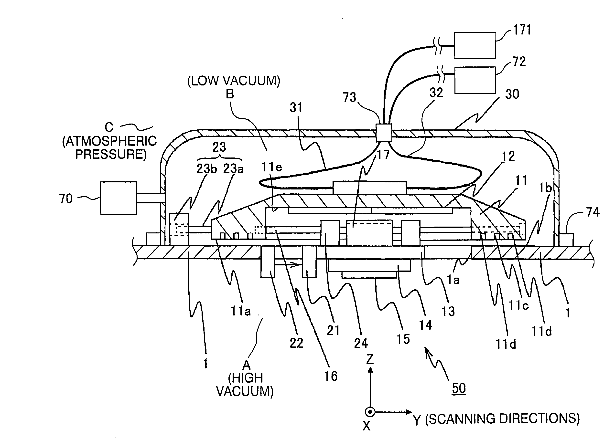
[0014]FIG. 1 shows a stage apparatus 50 according to a first embodiment of the present invention. In an exposure apparatus that uses, for example, a charged particle beam or EUV light as an exposure beam, the stage apparatus 50 is used to hold and drive a reticle 15 (mask). In the following explanation, the Z axis in FIG. 1 is perpendicular to a guide surface (which corresponds to a slide surface 1b of a vacuum chamber 1 discussed below; in the present embodiment, a substantially horizontal surface) for driving the reticle 15 (further, the −Z direction is vertically downward), the X axis is perpendicular to the paper surface in FIG. 1 within that guide surface, and the Y axis is parallel to the paper surface in FIG. 1. The exposure apparatus that comprises the stage apparatus 50 of the present embodiment is a scanning exposure type exposure apparatus that exposes the wafer by synchronously driving a reticle and a wafer (a substrate or a sensitive substrate), which is coated with a r...

second embodiment

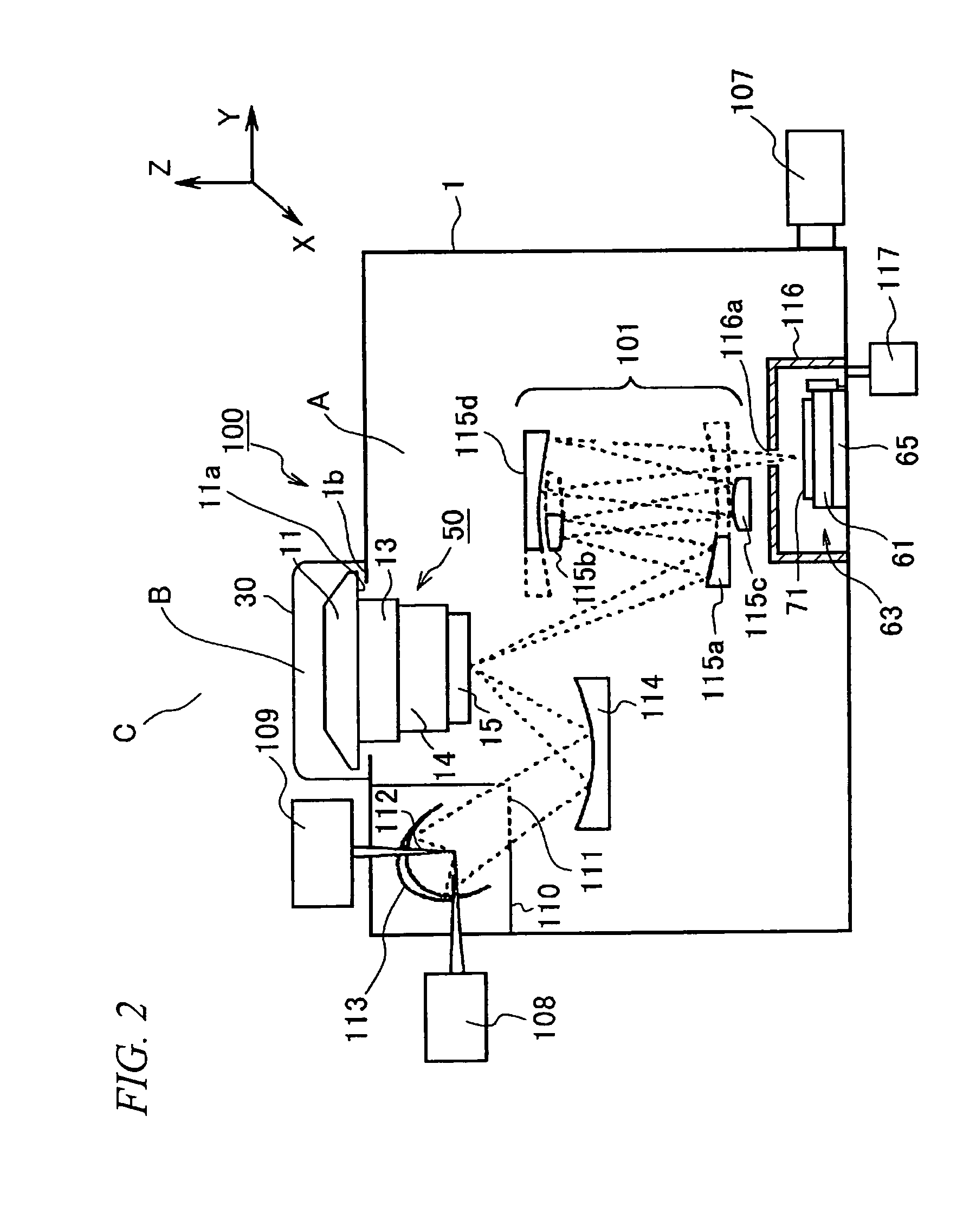
[0052]A second embodiment of the present invention will now be explained, referencing FIG. 2. In the present embodiment, the stage apparatus 50 of FIG. 1 is adapted to an exposure apparatus (EUV exposure apparatus) 100, which uses EUV light as the exposure beam. Members in FIG. 2 that are identical to those in FIG. 1 are assigned the identical symbols, and therefore detailed explanations thereof are omitted. In the present embodiment, it is preferable to use light with a wavelength in the range of 1-50 nm as the EUV light.

[0053]In FIG. 2, the exposure apparatus 100 comprises: the vacuum chamber 1, which has a large box shape and covers the optical path of the EUV light (the exposure beam); a laser plasma X-ray source, which generates EUV light; an illumination system, which illuminates the reflecting type reticle 15 with the EUV light; the stage apparatus 50 (reticle stage system), which is the same as that of the embodiment shown in FIG. 1 and holds and moves the reticle 15; an ima...


PUM

PropertyMeasurementUnit
gas pressureaaaaaaaaaa
mass ratioaaaaaaaaaa

Abstract

The present invention provides a stage apparatus wherein an object is disposed in an atmosphere with a gas pressure lower than atmospheric pressure, and the object can be driven with high accuracy. The stage apparatus that drives a reticle comprises: a vacuum chamber, which forms a space and has an opening; an integrated coarse and fine motion table, which has an electrostatic chuck that holds the object, that, when driven, moves the electrostatic chuck inside the space; a counter mass, which is disposed so that it covers the opening, that is capable of moving because of the reaction force produced when the integrated coarse and fine motion table is driven; and a vacuum cover, which forms a space that houses the counter mass; wherein the space and the space are set to prescribed gas pressures.

Description

CROSS-REFERENCE TO RELATED APPLICATION[0001]This is a Continuation Application of International Application No. PCT / JP2007 / 068647, filed Sep. 26, 2007, which claims priority to Japanese Patent Application No. 2006-266315, filed Sep. 29, 2006. The contents of the aforementioned applications are incorporated herein by reference.FIELD OF THE INVENTION[0002]The present invention relates to a stage apparatus that drives an object, an exposure apparatus that comprises the stage apparatus, and a device fabricating method wherein the exposure apparatus is used.DESCRIPTION OF RELATED ART[0003]In an exposure apparatus that uses a charged particle beam or extreme ultraviolet light (hereinbelow, called EUV light) with a wavelength of, for example, approximately 100 nm as an exposure beam to expose a substrate, such as a wafer, via a mask, exposures are generally performed in a vacuum with a gas pressure that is lower than atmospheric pressure in order to prevent the exposure beam from being abs...

Claims


Application Information

Patent Timeline
Patent Type & Authority Applications(United States)
IPC IPC(8): G01N21/00A61N5/00
CPCB82Y10/00B82Y40/00G03F7/70716G03F7/70766H01J37/3174G03F7/70808G03F7/70816G03F7/70841G03F7/70858G03F7/70783
Inventor TANAKA, KEIICHI
Owner NIKON CORP
Why Eureka
Try Eureka