Non-orthogonal particle detection systems and methods
a particle detection and non-orthogonal technology, applied in the field of optical particle counters, can solve the problems of particle counters that lack the ability to spatially resolve scattered or emitted electromagnetic radiation in a direction parallel to the fluid flow direction, and achieve the effect of improving the detection sensitivity of particle detection systems
- Summary
- Abstract
- Description
- Claims
- Application Information
AI Technical Summary
Benefits of technology
Problems solved by technology
Method used
Image
Examples
example 1
Particle Detector Images and Counting Efficiencies
[0058]FIGS. 4A, 4B, and 4C show images detected by a two-dimensional detector of a particle detection system embodiment for various angles between the flow direction and beam cross sectional profile major axis. These grey-scale images represent intensities observed by a two-dimensional detector where black is low intensity and white is high intensity. These images represent a view of the flow cell similar to that of FIG. 3E. In these images, the bright white spot at the top of the image represents scattered or emitted electromagnetic radiation generated by the beam interacting with the walls of the flow cell where the beam enters the flow cell. The bright white spot at the bottom of the image represents scattered or emitted electromagnetic radiation generated by the beam interacting with the walls of the flow cell where the beam exits the flow cell. In these images, particles having a size of 125 nm are travelling in the fluid along ...
example 2
Capillary Mount for Particle Counting with Integral Seals
[0063]One issue that has plagued liquid particle counters is the lack of a chemically resistant seal for sealing sample capillaries to a flow cell. An approach to solve this problem uses a holder or a mount comprising a nonreactive and virtually rigid polymer, for example Kel-f at 80 Shore D, to create a seal with a capillary inlet. The holder or mount includes one or more concentric seals around a capillary aperture integral to the holder or mount. This cuts the number of potential leak paths, eliminates components that can be incorrectly installed and reduces the number of tolerances to insure a more uniform seal pressure. In embodiments, a particle counter or particle detection system comprises such a capillary mount.
[0064]Imaging-based particle counters of the present invention optionally include capillary mounts for particle counting with integral seals, for example, using a rigid polymer (e.g., Kel-f at 80 Shore D) that ...
example 3
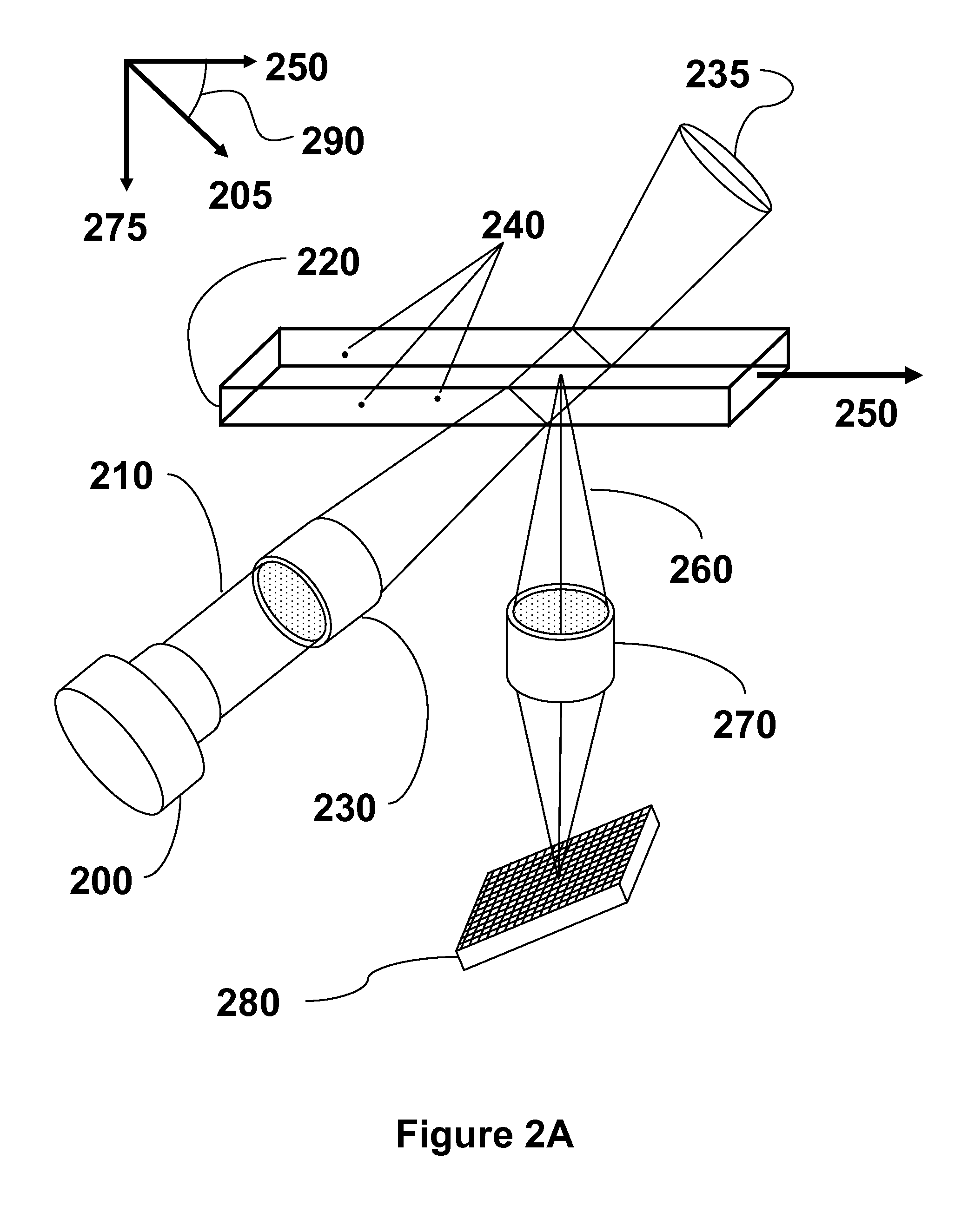
[0069]In embodiments, electromagnetic radiation is scattered from or emitted by a particle interacting with a beam of electromagnetic radiation of a particle detection system; scattered or emitted electromagnetic radiation which reaches the two-dimensional detector is detected, thereby generating a plurality of output signals corresponding to intensities of the scattered or emitted electromagnetic radiation. These output signals can be further processed and / or analyzed to determine a characteristic of the particle.
[0070]For some embodiments, output signals from every element of the two-dimensional detector are recorded or transmitted to a processor for further analysis. For other embodiments, however, output signals from a sub-array (i.e., only a portion) of the elements of the two dimensional detector are recorded or transmitted to a processor for further analysis. In this way, it is possible to select a subset of the two-dimensional detector for use in det...
PUM
| Property | Measurement | Unit |
|---|---|---|
| angle | aaaaa | aaaaa |
| width | aaaaa | aaaaa |
| width | aaaaa | aaaaa |
Abstract
Description
Claims
Application Information
 - R&D
- Intellectual Property
- Life Sciences
- Materials
- Tech Scout
- Unparalleled Data Quality
- Higher Quality Content
- 60% Fewer Hallucinations
Browse by: Latest US Patents, China's latest patents, Technical Efficacy Thesaurus, Application Domain, Technology Topic, Popular Technical Reports.
© 2025 PatSnap. All rights reserved.Legal|Privacy policy|Modern Slavery Act Transparency Statement|Sitemap|About US| Contact US: help@patsnap.com


