Anti-reflection coating, optical member, exchange lens unit and imaging device

an anti-reflection coating and lens technology, applied in the field of anti-reflection coating, optical member, exchange lens unit and imaging device, can solve the problems of large reflection loss, reduced contrast, resultant photographs with flare and ghosting

Active Publication Date: 2009-09-03
RICOH IMAGING COMPANY
View PDF2 Cites 21 Cited by
  • Summary
  • Abstract
  • Description
  • Claims
  • Application Information

AI Technical Summary

Benefits of technology

[0139]The seven-layer anti-reflection coating of the present invention has

Problems solved by technology

Because reflection is superimposed in and between the lenses, large reflection loss of each lens provides the resultant photographs with flare and ghost, as well as reduced contrast.
An anti-reflection coating having such structure serves to make tarnish and scratches, if any, on the substrate surface less conspicuous, but it has poor anti-reflection performance, and fails to filly prevent tarnish.
Although this anti-reflection coating has a tarnish-preventing function because the first layer is made of alumina, its anti-reflection performance to visible light in wavelength of around 400 nm or 700 nm is insufficient.
However, because the reflectance is about 0.1%, this anti-reflection coating has transmittance of about 96% when applied to 20 lenses, resulting in reflection loss of about 4%.
However, it has as large reflectance as more than 0.5% to visible light near a wavelength of 400 nm, and fails to fully prevent tarnish.
Although this anti-reflection coating has a tarnish-preventing function because the innermost layer is made of alumina, it does not have sufficient reflectance to visible light near a wavelength of 400 nm.
However, because the innermost layer is made of Ta2O5 or ZrO2, tarnish cannot be fully suppressed.

Method used


Image

  • Anti-reflection coating, optical member, exchange lens unit and imaging device
  • Anti-reflection coating, optical member, exchange lens unit and imaging device
  • Anti-reflection coating, optical member, exchange lens unit and imaging device

Examples


example 1

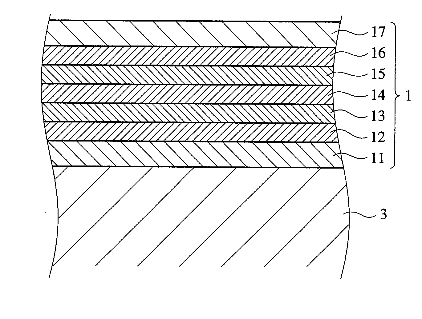
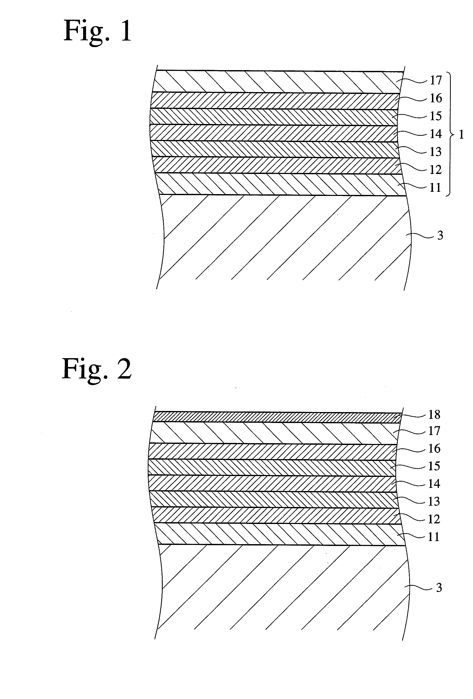
[0121]An anti-reflection coating 1 having the layer structure shown in Table 1 was produced by the following steps. The refractive index of each layer was measured with light having a wavelength of 550 nm.

[0122][1] Formation of First to Sixth Layers

[0123]Using the apparatus shown in FIG. 7, the first to sixth layers shown in Table 1 were formed on an optical lens of LF5 by an electron-beam vacuum vapor deposition method at an initial degree of vacuum of 1.2×10⁻⁵ Torr and a substrate temperature of 230° C.

[0124][2] Formation of Seventh Layer

[0125]A silica aerogel layer as the seventh layer was formed by a sol-gel method comprising the following steps.

[0126](2-i) Preparation of Wet Silica Gel

[0127]After 5.21 g of tetraethoxysilane and 4.38 g of ethanol were mixed, 0.4 g of hydrochloric acid (0.01 N) was added, and stirring was conducted for 90 minutes. With 44.3 g of ethanol and 0.5 g of ammonia water (0.02 N) added, stirring was conducted for 46 hours, and then this mixed solution wa...

example 2

[0134]An anti-reflection coating having the layer structure shown in Table 2 was formed in the same manner as in Example 1.

TABLE 2RefractiveOpticalNo.MaterialIndexThickness (nm)SubstrateLF51.584—First LayerAl2O31.650200.0Second LayerTa2O5 + Y2O3 + Pr6O112.05050.0Third LayerMgF21.38052.5Fourth LayerTa2O5 + Y2O3 + Pr6O112.05060.0Fifth LayerMgF21.38090.0Sixth LayerTa2O5 + Y2O3 + Pr6O112.05025.0Seventh LayerSilica Aerogel1.150130.0MediumAir1.000—

example 3

[0135]An anti-reflection coating having the layer structure shown in Table 3 was formed in the same manner as in Example 1.

TABLE 3RefractiveOpticalNo.MaterialIndexThickness (nm)SubstrateKF31.466—First LayerAl2O31.650147.5Second LayerZrO2 + TiO22.11040.4Third LayerSiO21.46247.1Fourth LayerZrO2 + TiO22.11053.9Fifth LayerSiO21.46290.3Sixth LayerZrO2 + TiO22.11021.1Seventh LayerSilica Aerogel1.150143.0MediumAir1.000—


PUM

PropertyMeasurementUnit
wavelengthaaaaaaaaaa
wavelength rangeaaaaaaaaaa
reflectanceaaaaaaaaaa

Abstract

An anti-reflection coating comprising first to seventh layers formed on a substrate in this order, the first layer being an alumina-based layer, the seventh layer being a porous, silica-based layer, and each of the first to seventh layers having predetermined refractive index and optical thickness in a wavelength range of 400-700 nm.

Description

FIELD OF THE INVENTION[0001]The present invention relates to an anti-reflection coating having excellent anti-reflection performance and tarnish-preventing effect on a glass substrate having a low to medium refractive index, thus suitable for exchange lens units for single-lens reflex cameras, etc., an optical member comprising such an anti-reflection coating, and an exchange lens unit and an imaging device comprising such an optical member.BACKGROUND OF THE INVENTION[0002]A high-performance, single-focus or zoom lens unit for single-lens reflex cameras, etc. generally has about 10-40 lenses in a lens barrel. Each lens has a laminated anti-reflection coating comprising pluralities of dielectric layers each having a different refractive index from that of a lens substrate and a thickness of ½λ or ¼λ, wherein λ is a center wavelength, to utilize interference effects.[0003]For instance, when an anti-reflection coating formed on each of 20 lenses has reflectance of 0.5%, its transmittan...

Claims


Application Information

Patent Timeline
Patent Type & Authority Applications(United States)
IPC IPC(8): G02B1/11G02B1/111G02B1/18H04N5/225
CPCG02B2207/107G02B1/115G02B1/11
Inventor YAMADA, KAZUHIRONAKAYAMA, HIROYUKISUZUKI, MINETA
Owner RICOH IMAGING COMPANY
Why Eureka
Try Eureka