Image forming apparatus

Active Publication Date: 2009-09-10
RICOH KK
View PDF3 Cites 0 Cited by
  • Summary
  • Abstract
  • Description
  • Claims
  • Application Information

AI Technical Summary

Benefits of technology

[0020]The present invention has been made in view of the aforementioned circumstances and it is an object of at least one embodiment of the present invention to provide an image forming apparatus capable of reducing droop and moderating skew even when the number of beam channels is increased.
[0023]According to one embodiment, droop can be reduced and skew can be moderated.

Problems solved by technology

However, the number of rotations, response speeds of beam pulses and the photosensitive body, and the like of this scanning optical method are not becoming high enough to meet market demands for electrophotography at higher speed.
When channels of laser beams are increased in such laser devices, distortions of an optical system such as skewed and bowed scanning lines, are generated.
In the case of increasing the number of beam channels by using, for example, an array type laser head in Patent Documents 1 to 4, there is a problem in that changes in the amount of light (droop) are increased due to increased temperature of such light sources.
As a result, there is a problem in that skew is increased.
The method of Patent Document 5 cannot solve both correction of skew of a scanning line generated by multi-beam scanning, and elimination of droop.

Method used


Image

  • Image forming apparatus
  • Image forming apparatus
  • Image forming apparatus

Examples


embodiment

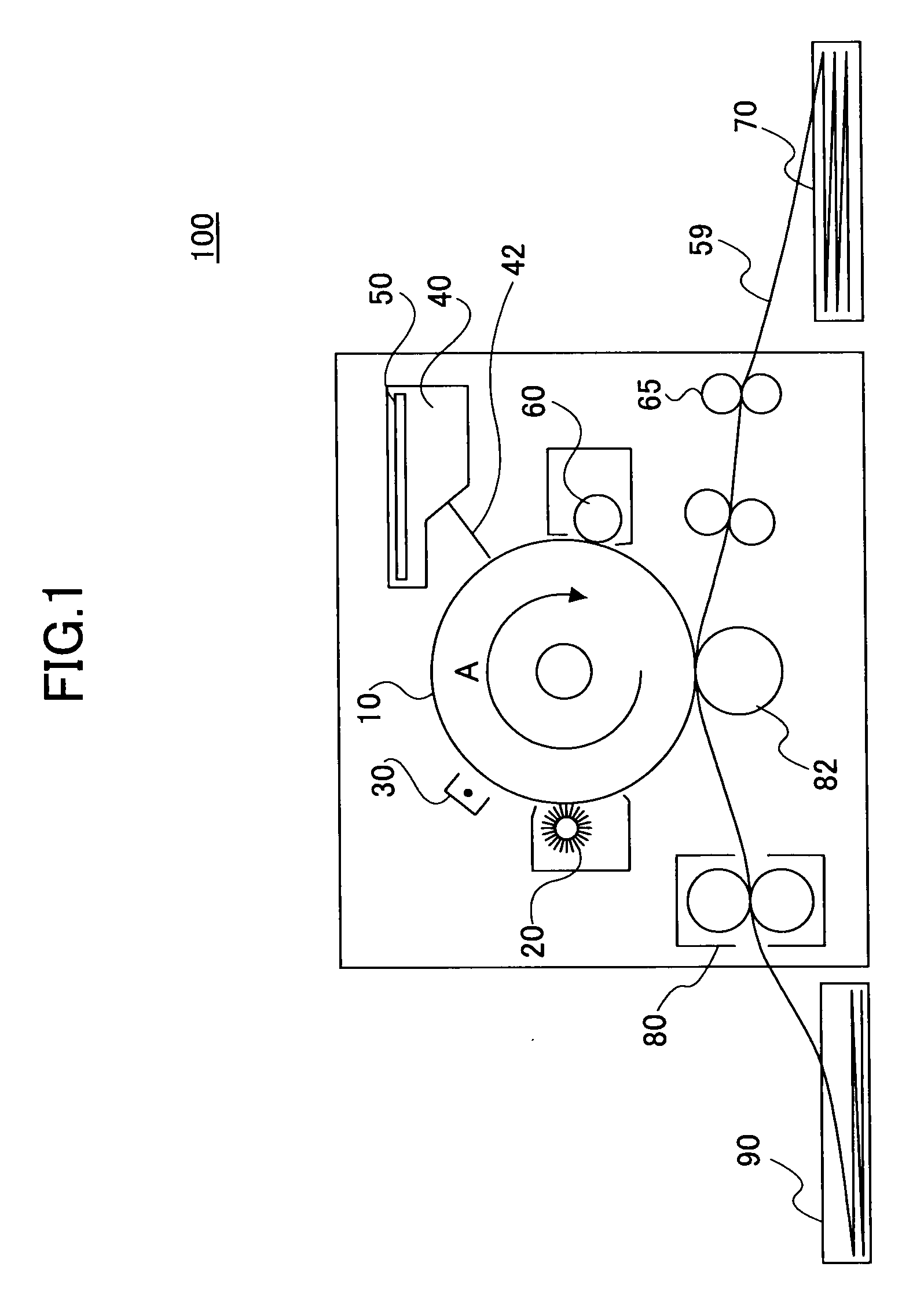
[0040]Hereinafter, an embodiment of the present invention is described with reference to the drawings. FIG. 1 is a schematic diagram showing an image forming apparatus 100 of the present invention.

[0041]The image forming apparatus 100 includes a photosensitive drum 10, a cleaning roller 20, a charger 30, a laser unit 40, a controller 50, a developing roller 60, a paper supply stacker 70, a fixer 80, and a paper output stacker 90.

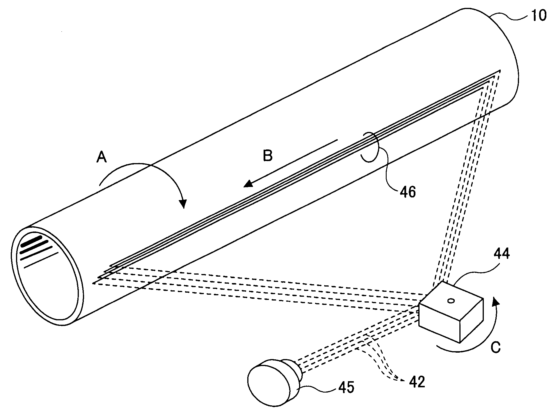
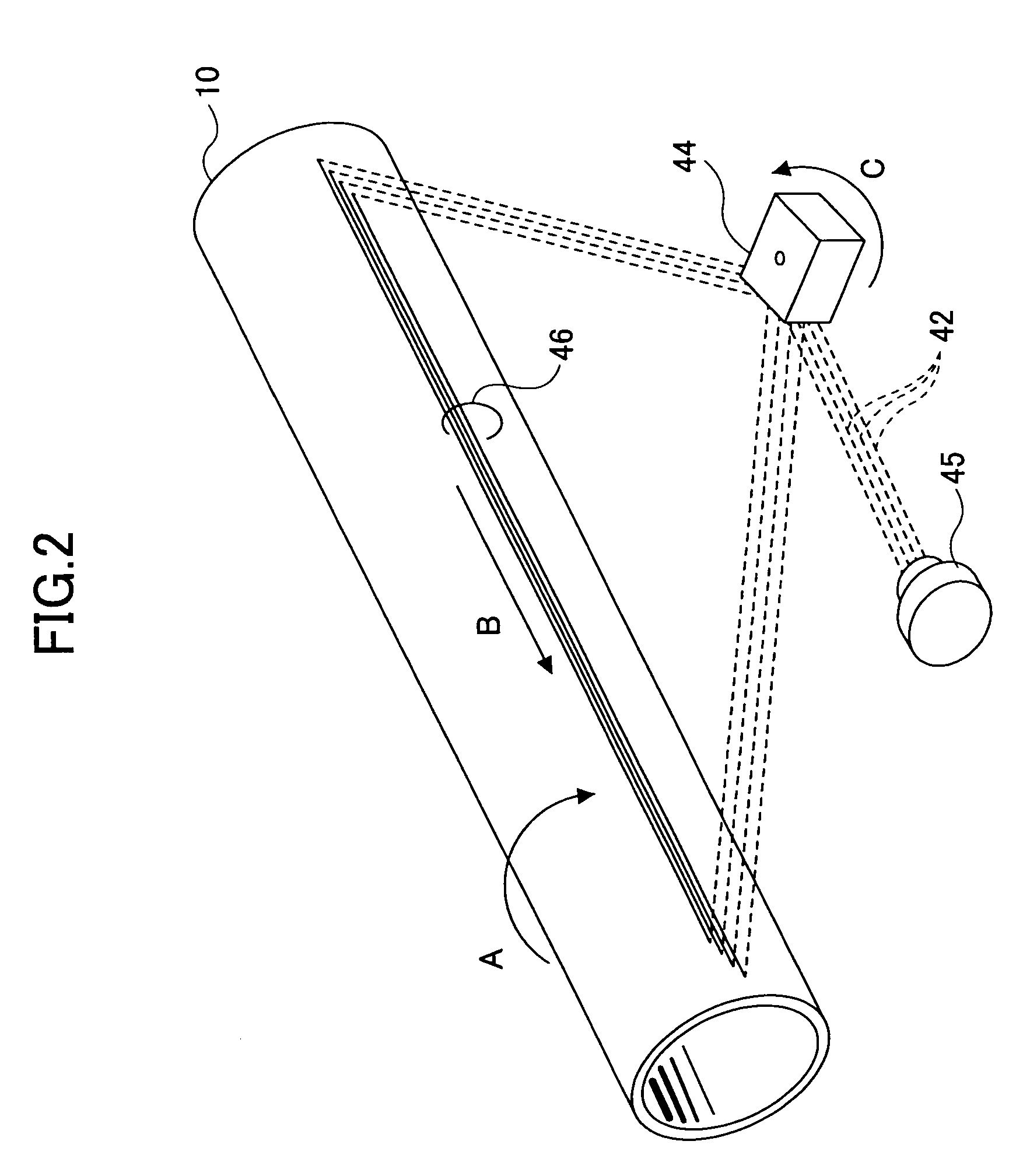
[0042]The photosensitive drum 10 rotates in the direction of arrow A shown in FIG. 1. A laser beam is emitted from the laser unit 40, and thereby an electrostatic latent image is formed on the photosensitive body drum 10. After a surface of the photosensitive body drum 10 is cleaned by the cleaning roller 20, the charger 30 charges the surface of the photosensitive body drum 10. The controller 50 controls the laser unit 40. The laser unit 40 turns on / off the laser beams 42 emitted in response to signals from the controller 50 so as to scan the surface of the...


PUM


Abstract

A disclosed image forming apparatus includes a laser array light source having plural laser light sources for generating plural laser beams; a photosensitive body having a surface on which an electrostatic latent image is formed by a surface potential changed by the plural laser beams emitted from the laser array light source; and a controller for controlling emission of the plural laser beams of the laser array light source. The controller sequentially turns off at least one of the plural laser beams when forming a continuous electrostatic latent image line on the photosensitive body by scanning the plural laser beams in a main scanning direction of the photosensitive body.

Description

BACKGROUND OF THE INVENTION[0001]1. Field of the Invention[0002]The present invention generally relates to an image forming apparatus having a laser array light source.[0003]2. Description of the Related Art[0004]Conventionally, electrophotographic image forming apparatuses have employed a scanning optical method to form a scanning line on a photosensitive body by irradiating a rotating polygon mirror with a laser beam to scan onto the photosensitive body. However, the number of rotations, response speeds of beam pulses and the photosensitive body, and the like of this scanning optical method are not becoming high enough to meet market demands for electrophotography at higher speed.[0005]Therefore, an edge emitting type array laser head having plural light emitting units provided linearly as disclosed in Patent Document 1 and a surface emitting type laser head having plural light emitting units arranged in a matrix as disclosed in Patent Document 2 are being developed as a laser dev...

Claims


Application Information

Patent Timeline
IPC IPC(8): B41J2/435
CPCG03G15/326B41J2/473G03G15/0435G03G15/04072
Inventor SHIBUYA, TAKESHI
Owner RICOH KK
Why Eureka
Try Eureka