Multi-antenna module

a technology of multi-antenna modules and antennas, applied in the field of multi-antenna modules, can solve the problems of increasing the difficulty of installing the antenna integration system, the radiation efficiency of the antenna integration system is difficult to increase, and the antenna system is difficult to integrate with electronic products, so as to reduce the layout space of the antenna, reduce the interference between the antenna and the effect of reducing the interferen

Inactive Publication Date: 2009-09-17
ADVANCED CONNECTEK INC
View PDF9 Cites 30 Cited by
  • Summary
  • Abstract
  • Description
  • Claims
  • Application Information

AI Technical Summary

Benefits of technology

[0016]In the second embodiment, the framework of parallel primary radiation arm and secondary radiation arm can infinitely expand the number of antenna units in the same antenna structure. Filters, which can effectively reduce the interference between antennae, can be formed via appropriately adjusting the capacitive coupling effect of parallel radiation arms and the inductance of the radiation conductors. Thereby, multiple antennae can be integrated into the same antenna structure to share the radiation conductors and greatly reduce the layout space of antennae. Thus, the present invention can achieve antenna miniaturization and multiple operation frequency bands and apply to many communication systems. Further, the present invention is easy-to-assemble for various electronic devices

Problems solved by technology

Such a layout should increase the difficulty of installing the antenna integration system and make the antenna system hard to integrate with electronic products.
However, the radiation efficiency of the antenna integration system is hard to obviously increase thereby.
In fact, the prior-art antenna integration system seldom achieves the announced function completely.

Method used


Image

  • Multi-antenna module
  • Multi-antenna module
  • Multi-antenna module

Examples


first embodiment

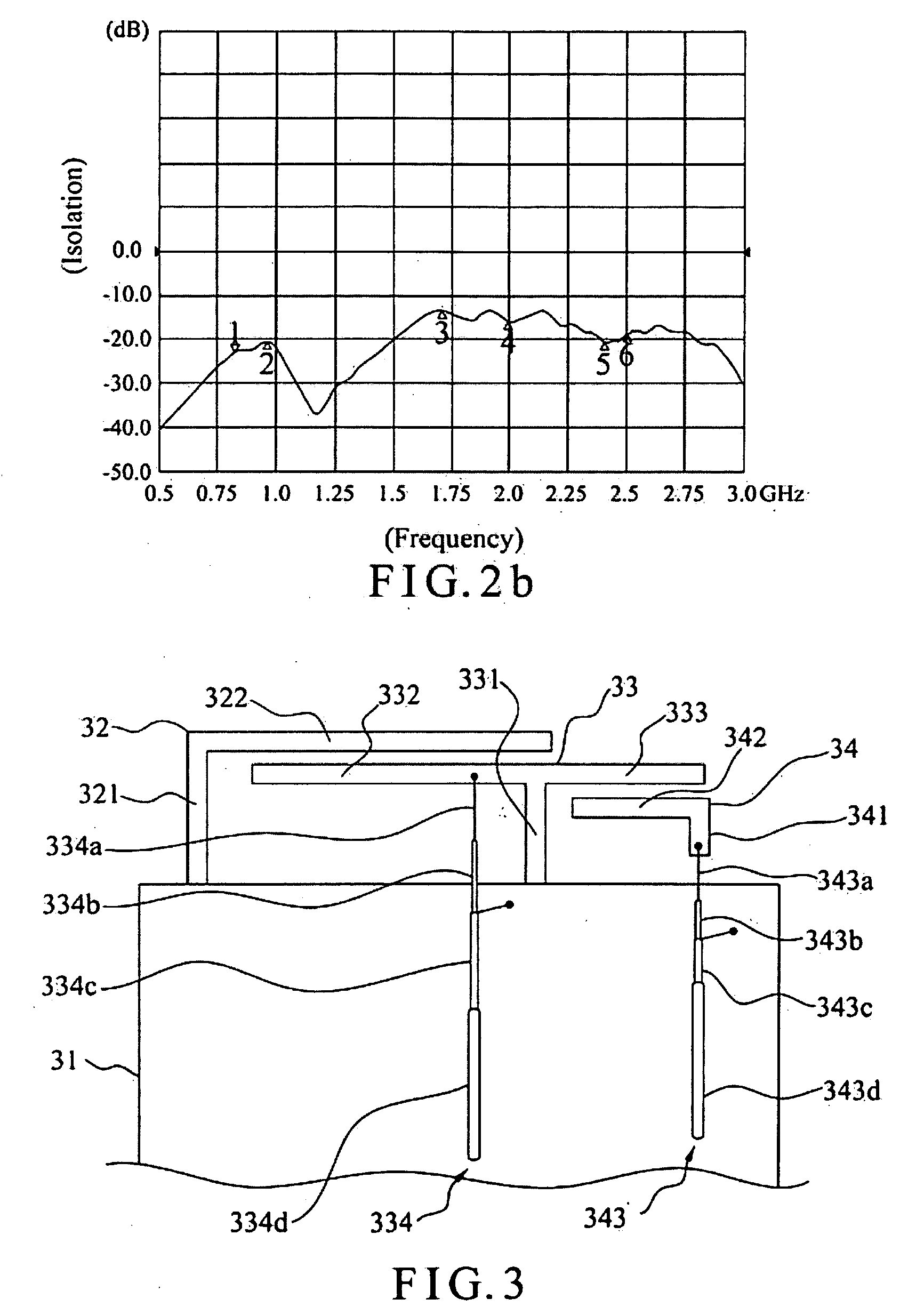
[0031]Referring to FIG. 3 a top view of a multi-antenna module according to the present invention, the multi-antenna module of the present invention comprises a ground plane 31, a primary conductor 32, a secondary conductor 33 and a coupling conductor 34. The primary conductor 32 further comprises a first short-circuit member 321 and a primary radiation arm 322. The secondary conductor 33 further comprises a second short-circuit member 331, a secondary radiation arm 332, an extension arm 333 and a first feeder cable 334. The coupling conductor 34 further comprises a feeder member 341, a coupling arm 342 and a second feeder cable 343.

[0032]One end of the first short-circuit member 321 of the primary conductor 32 is connected to the ground plane 31. One end of the primary radiation arm 322 is connected to the other end of the first short-circuit member 321, and the primary radiation arm 322 extends from the first short-circuit member 321 along a first direction. One end of the second ...

second embodiment

[0043]The second embodiment incorporates multiple antenna units in the framework of the parallel primary radiation arm 522 and secondary radiation arm 532, wherein a capacitive coupling effect is created between the parallel radiation arms, and inductance is created in the radiation conductor 34. Different-frequency filters can be formed via appropriately adjusting the capacitive coupling effect and the inductance to respectively isolate antennae lest they interfere mutually. Thus is formed a multi-antenna module sharing radiation conductors, achieving antenna miniaturization, simplifying assembly procedures, having multiple operation frequency bands and applying to multiple communication systems.

[0044]Referring to FIG. 6, a perspective view schematically shows that the second embodiment applies to a portable computer. The multi-antenna module of the present invention is arranged in the inner edge of a baseplate 61 of a portable computer 6. The ground plane 51 is made of a tin foil....


PUM


Abstract

A multi-antenna module comprises a ground plane, a primary conductor, a secondary conductor and a plurality of coupling conductors, wherein the framework of the parallel primary radiation arm and secondary radiation arm can infinitely expand the number of antenna units in the same antenna structure. The capacitive coupling effect of parallel radiation arms and the inductance of the radiation arms themselves can effectively reduce the signal interference between antennae, whereby a plurality of antennae can be integrated to achieve antenna miniaturization. The primary conductor, the secondary conductor and the coupling conductors are all connected to the same ground plane, whereby the layout space is reduced, and the multi-antenna module is easy-to-assemble for various electronic devices.

Description

BACKGROUND OF THE INVENTION[0001]1. Field of the Invention[0002]The present invention relates to a multi-antenna module, particularly to a multi-antenna module, wherein the number of antenna units can be infinitely expanded in the same antenna structure.[0003]2. Description of the Related Art[0004]With the popularization of wireless communication, there are also many advances in antenna technology. Particularly, many types of Combo antenna systems have been developed to meet the tendency of miniaturizing antennae and fabricating multi-frequency communication devices, wherein different antenna structures are integrated into a single antenna module to attain a multi-frequency function and reduce the sizes of antenna systems.[0005]Refer to FIG. 1. A Taiwanese patent No. 1268010 discloses an antenna integration system for mobile phones, which comprises a baseplate 104, a planar Inverted F antenna 101, a monopole antenna 102, and a planar antenna 103. The planar Inverted F antenna 101 ha...

Claims


Application Information

Patent Timeline
Patent Type & Authority Applications(United States)
IPC IPC(8): H01Q9/04
CPCH01Q1/243H01Q21/28H01Q9/42
Inventor CHIU, TSUNG-WENLIN, SHENG-CHIHTSENG, YI-WEIHSIAO, FU-REN
Owner ADVANCED CONNECTEK INC
Why Eureka
Try Eureka