Near Infrared Ray Reflective Substrate And Near Infrared Ray Reflective Laminated Glass Employing That Substrate, Near Infrared Ray Reflective Double Layer Glass

a technology of reflective laminated glass and near infrared ray reflective laminated glass, which is applied in the field of heat-reflective substrates, can solve the problems of insufficient heat-insulating effect, increase in thickness and weight, and increase in lamination glass, and achieve good heat-insulating effect and high visible light transmittan

Inactive Publication Date: 2009-09-24
CENT GLASS CO LTD
View PDF10 Cites 69 Cited by
  • Summary
  • Abstract
  • Description
  • Claims
  • Application Information

AI Technical Summary

Benefits of technology

[0009]The present invention was made for solving problems of near-infrared reflective laminated glasses according to such prior art techniques, and provides a near-infrared reflective substrate, a near-infrared reflective laminated glass and a near-infrared reflective double glazing, which are high in visible light transmittance defined in JIS R3106-1998, have a good heat insulation effect due to high reflectance of near-infrared region, and transmit various radio waves.

Problems solved by technology

This laminated glass has a weakness that the thickness and the weight increase, as compared with current laminated glasses.
It is, however, not possible to obtain a sufficient heat insulation, since the reflectance of near-infrared region is small in the reflection by the interference film of Patent Publication 2.
If conductive films are used, radio waves in a wide-range frequency band, such as television, radio, ETC, wireless LAN and cellular phone, are not transmitted, and at the present time, at which communication systems by various radio waves are constructed, communication systems by radio waves are not utilized, thereby making it difficult to use them for architectural and vehicular windows.

Method used


Image

  • Near Infrared Ray Reflective Substrate And Near Infrared Ray Reflective Laminated Glass Employing That Substrate, Near Infrared Ray Reflective Double Layer Glass
  • Near Infrared Ray Reflective Substrate And Near Infrared Ray Reflective Laminated Glass Employing That Substrate, Near Infrared Ray Reflective Double Layer Glass
  • Near Infrared Ray Reflective Substrate And Near Infrared Ray Reflective Laminated Glass Employing That Substrate, Near Infrared Ray Reflective Double Layer Glass

Examples


example 1

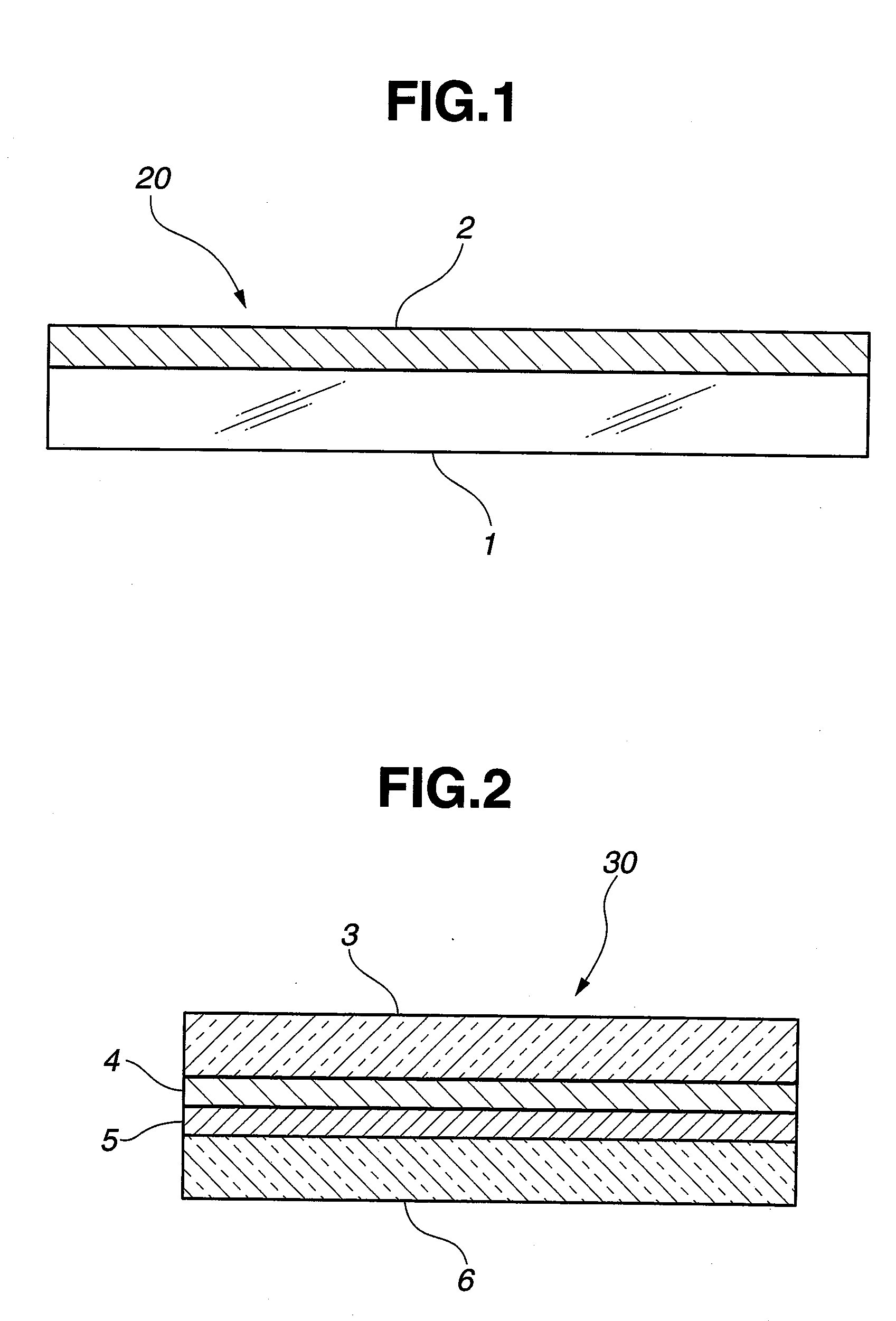
[0073]There was produced a near-infrared reflective substrate 20 shown in FIG. 1. As the transparent substrate 1, there was used a plate glass 3 (see FIG. 2) of a transparent soda-lime glass produced by float process, having a size of 1000 mm×1000 mm and a thickness of 2 mm.

[0074]This plate glass was washed and dried and set in a sputtering film forming apparatus. Five layers of dielectric films were deposited on the surface to form a near-infrared reflective film 2.

[0075]The dielectric films constituting the near-infrared reflective film 2 were formed by film formations of TiO2 film (thickness: 105 nm), SiO2 film (thickness: 175 nm), TiO2 film (thickness: 105 nm), SiO2 film (thickness: 175 nm) and TiO2 film (thickness: 105 nm) in this order from the glass surface. Electric resistance of the dielectric film stacks was measured, and it was almost infinite.

[0076]The visible light transmittance defined by JIS R3106-1998 of this near-infrared reflective substrate was 83%. As the reflect...

example 2

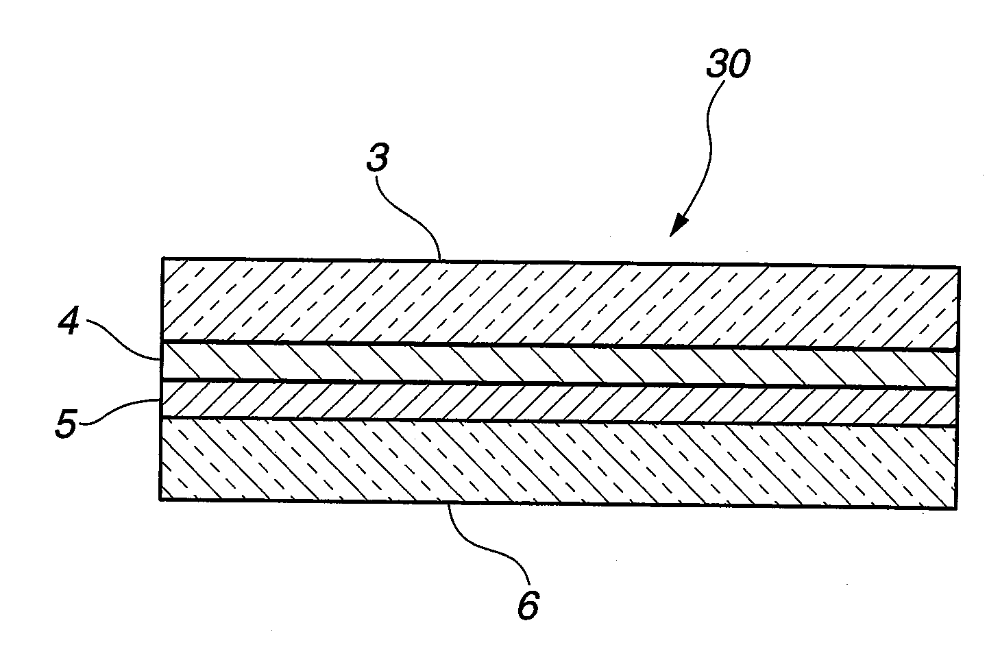
[0077]Using the near-infrared reflective substrate 20 produced in Example 1, there was produced a near-infrared reflective laminated glass shown in FIG. 2.

[0078]A near-infrared reflective film 4 was positioned on the side of an interlayer film 5. A PVB film having a thickness of 0.76 mm was used as the interlayer film 5.

[0079]As a plate glass 6, there was used the same plate glass as the plate glass 3 used in Example 1.

[0080]The near-infrared reflective substrate 20 (i.e., a laminate of the plate glass 3 and the near-infrared reflective film 4 in FIG. 2) produced in Example 1, the interlayer film 5 and the plate glass 6 were laminated together, followed by a pressurization / heating treatment, thereby producing a near-infrared reflective laminated glass 30 in which the near-infrared reflective substrate 20 produced in Example 1 and the plate glass 6 are bonded together by the interlayer film 5.

[0081]The visible light transmittance defined by JIS R3106-1998 of the near-infrared reflect...

example 3

[0083]A near-infrared reflective substrate 20 shown in FIG. 1 was produced in the same manner as that of Example 1, except in that the near-infrared reflective film 2 was formed by dielectric films of seven layers.

[0084]The near-infrared reflective film 2 was constituted by dielectric films of seven layers by sequential deposition of Nb2O5 film (thickness: 115 nm), SiO2 film (thickness: 175 nm), Nb2O5 film (thickness: 115 nm), SiO2 film (thickness: 175 nm), Nb2O5 film (thickness: 115 nm), SiO2 film (thickness: 175 nm), and Nb2O5 film (thickness: 115 nm) on the glass surface of the plate glass 1.

[0085]By the measurement of electric resistance of these dielectric films of seven layers, it was confirmed to be almost infinite and to have no problem in transmission of electromagnetic waves, similar to Example 1.

[0086]The visible light transmittance defined by JIS R3106-1998 of this near-infrared reflective substrate was 81%. As the reflection characteristics of the plate glass surface we...


PUM

PropertyMeasurementUnit
transparentaaaaaaaaaa
thicknessaaaaaaaaaa
thicknessaaaaaaaaaa

Abstract

In a near-infrared reflective substrate prepared by forming on a transparent substrate a near-infrared reflective film prepared by alternate deposition of low-refractive-index dielectric films and high-refractive-index dielectric films, there is provided a near-infrared reflective substrate characterized in that the transparent substrate is a plate glass or polymer resin sheet, that it is 70% or greater in visible light transmittance defined in JIS R3106-1998, and that it has a maximum value of reflection that exceeds 50% in a wavelength region of 900 nm to 1400 nm.

Description

TECHNICAL FIELD[0001]The present invention relates to a heat-ray reflective substrate, which is used for lowering the temperature increase of the transmission side of a vehicular or architectural window, which is caused by thermal radiation of the sunshine, and for lowering the temperature increase caused by thermal radiation of the sunshine falling directly on a display, and a laminated glass and a double glazing using such heat-ray reflective substrate.BACKGROUND OF THE INVENTION[0002]There are many proposals of making a comfortable interior space by restricting the temperature increase of an interior through lowering the thermal radiation energy of the sunshine flowing into the interior through the window glass, by restricting the electric energy consumption consumed by driving an air-cooling apparatus, and by maintaining a high visible light transmittance of the window glass.[0003]It is proposed by Patent Publication 1 that, in a laminated glass having an interlayer film between...

Claims


Application Information

Patent Timeline
Patent Type & Authority Applications(United States)
IPC IPC(8): G02B5/28B32B37/00
CPCB32B17/10Y10T156/10B32B17/10174B32B17/10761C03C17/007C03C17/3417C03C27/06C03C27/10C03C2217/475C03C2217/476C03C2217/734G02B5/208G02B5/282G02B5/285B32B17/10036B32B2367/00B32B17/10005
Inventor TAKAMATSU, ATSUSHIYONEKURA, MASAAKIOMOTO, HIDEONAKAMURA, ISAO
Owner CENT GLASS CO LTD
Why Eureka
Try Eureka