
Press fit (compliant) terminal and other connectors with tin-silver compound

a technology of tin-silver compound and terminal, which is applied in the direction of coupling contact members, line/current collector details, printed circuits, etc., can solve the problems of increasing contact resistance and increasing so as to reduce the coefficient of friction and increase the risk of short circuit. , the effect of less friction

Inactive Publication Date: 2009-09-24
INTERPLEX IND
View PDF4 Cites 58 Cited by
  • Summary
  • Abstract
  • Description
  • Claims
  • Application Information

AI Technical Summary

Benefits of technology

[0008]The tin-silver compound that is provided as a coating on the terminal serves to prevent the formation of tin whiskers which appear most frequently in pure tin coated electrical components under mechanical stress. Tin whiskers have been known to grow to lengths of tip to 10 mm, thereby increasing the risk of a short circuit caused by the tin whisker bridging the gap between electrical components. Preferably, the tin-silver compound includes between 85 and 99.5% weight of tin and between 0.5 and 15% weight of silver and is applied at a thickness range between 0.4 and 5 microns using a technique such as electroplating, hot dip or immersion. The relative proportion of tin and silver may be modified to thereby modify the temperature characteristics, such as melt temperature, to suit particular applications, such as high temperature applications.

Problems solved by technology

Tin whiskers have been known to grow to lengths of tip to 10 mm, thereby increasing the risk of a short circuit caused by the tin whisker bridging the gap between electrical components.
As a result of these small movements, the oxides near the contact points can be broken up, with fresh material being exposed to the atmosphere, resulting in oxidized wear debris in the contact area, which ultimately leads to an increase in contact resistance.

Method used


Image

  • Press fit (compliant) terminal and other connectors with tin-silver compound
  • Press fit (compliant) terminal and other connectors with tin-silver compound
  • Press fit (compliant) terminal and other connectors with tin-silver compound

Examples


Embodiment Construction

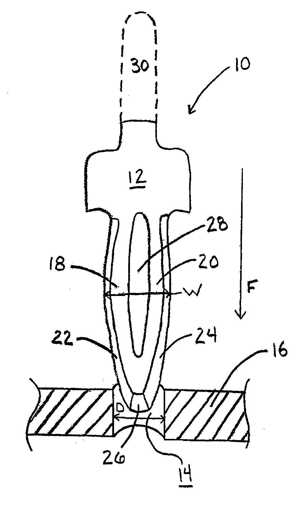
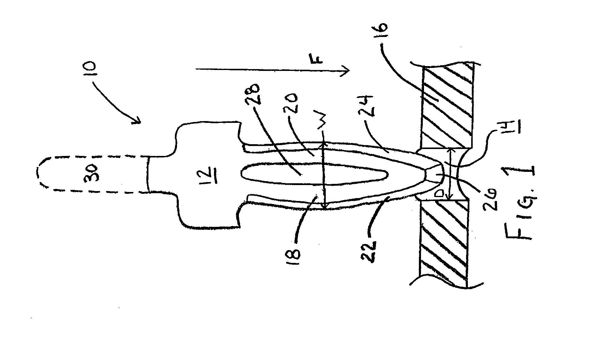
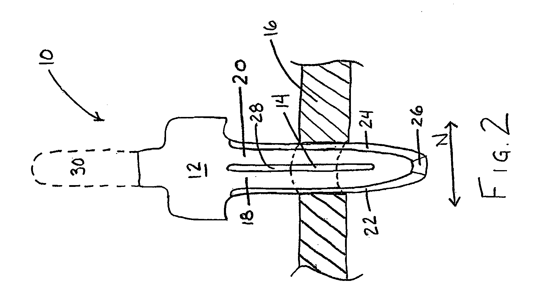
[0013]Referring to FIGS. 1 and 2, a press-fit interconnect, shown generally at 10 and which interfaces to an electrical component 30, is made up primarily of a terminal 12 which interfaces with a plated through-hole 14. In one embodiment, the terminal 12 includes right and left beams 18 and 20, having right and left outer edges 22 and 24, which merge at a tip 26. Between the right and left beams 18 and 20, is a needle-eye 28. The plated through-hole 14 is preferably a circular aperture through a PCB 16 having a diameter D which is less than the greatest width W of the terminal 12 measured between the outer peripheries of the right and left outer edges 22 and 24.

[0014]To assemble the press-fit interconnect 10 into a PCB 16, a force F is applied to the terminal 12 in order to press the tip 26 downwards into the plated through-hole 14. As the terminal 12 continues to be pressed downwards, the right and left beams 18 and 20 converge towards each another, thus narrowing the needle-eye 28...


PUM

PropertyMeasurementUnit
thicknessaaaaaaaaaa
widthaaaaaaaaaa
widthaaaaaaaaaa

Abstract

A tin-silver press-fit interconnect which includes a press-fit terminal having a coating or finish of a tin-silver compound for use with a terminal receiving device. The tin-silver compound serves to prevent the formation of tin whiskers which appear most frequently in pure tin coated electrical components under mechanical stress and which make the electronic device susceptible to short circuits. The tin-silver compound may include between 85 and 99.5% weight of tin and between 0.5 and 15% weight of silver and is applied at a thickness range between 0.4 and 5 microns using a technique such as electroplating, hot dip or immersion.

Description

CROSS-REFERENCE TO RELATED APPLICATION[0001]The present application claims the benefit of U.S. Provisional Patent Application Ser. No. 61 / 038,159, filed Mar. 20, 2008, which is hereby incorporated by reference in its entirety.FIELD OF THE INVENTION[0002]The present invention generally relates to electrical connectors, and more specifically to press-fit terminals having a tin-silver coating.BACKGROUND OF THE INVENTION[0003]As part of a shift towards a cleaner, safer environment, the electronics industry has been eliminating the use of lead as a doping agent in tin component coatings, as well as in soldering materials and operations. These tin-lead compounds were used to create a coating or soldering material with a particular melting temperature by varying the relative amounts of tin and lead in the compound. For example, a tin-lead compound having 63% tin and 37% lead is eutectic, meaning that it has the lowest possible melting point for the mixture of the two components, melting at...

Claims


Application Information

Patent Timeline
Patent Type & Authority Applications(United States)
IPC IPC(8): H01R12/00H01R43/00
CPCH01R12/585Y10T29/49171H01R13/03
Inventor LYNCH, JOSEPH J.SCHNEIDER, RICHARD
Owner INTERPLEX IND
Learn More