Method of fluorescence-microscopically imaging a structure in a sample with high three-dimensional spatial resolution

a fluorescence-microscopic imaging and structure technology, applied in the field of three-dimensional spatial resolution fluorescence-microscopic imaging a structure in a sample, can solve the problem of not achieving any increase in spatial resolution, and achieve the effect of facilitating upgrading and facilitating the application of the new method

Inactive Publication Date: 2009-10-01
MAX PLANCK GESELLSCHAFT ZUR FOERDERUNG DER WISSENSCHAFTEN EV
View PDF7 Cites 25 Cited by
  • Summary
  • Abstract
  • Description
  • Claims
  • Application Information

AI Technical Summary

Benefits of technology

[0020]Of course, there are further benefits of the new method, if the intensity of the transfer signal does not only decrease stronger with the distance to the common centre of maximum intensity than the effective return rate of the fluorophore in the direction of the optical axis of the common objective but also laterally thereto, i.e. within the focal plane of the common objective.
[0033]The high three-dimensional spatial resolution of the new method due to the multiplication of the PSF of the excitation signal by the PSF of the transfer signal may not only be used in three-dimensionally scanning a sample, although this application of the new method is a preferred embodiment. The high three-dimensional spatial resolution of the method of the present invention is a substantial advantage, even if the sample is only scanned in one or two dimensions. For three-dimensionally scanning the sample, the common centre of maximum intensity of the transfer signal and the excitation signal is shifted with regard to the sample in three linearly independent directions to completely cover at least one area of the sample extending in all three dimensions.
[0035]In addition, a maximum benefit is only obtained from the new method, if the transfer signal and the excitation signal are both below a saturation intensity above which the proportion of the fluorophore transferred into its second photochromic state or excited for fluorescence is no longer linearly correlated to the intensity of the transfer signal or the excitation signal. In general, saturation should be avoided in all transitions involved, as it would potentially reduce the spatial resolution.
[0037]Particularly, the return signal may be a pulsed signal completely returning the fluorophore into the first photochromic state prior to the steps of subjecting the sample to the transfer signal and the excitation signal and of detecting fluorescence light. This strong return signal strongly contributes to the relevant time-averaged spatial distribution of the effective return rate of the fluorophore. In fact, it ensures that the effective return rate of the fluorophore decreases less with the distance to the common centre of maximum intensity of the transfer signal and the excitation signal than the intensity of the transfer signal as required in the new method, even if the excitation signal, for example, induces a localized contribution to the effective return rate which as strongly decreases with the distance to the common centre of maximum intensity as the intensity of the transfer signal.
[0038]The absorption spectra of known photochromic fluorophores suitable for use in the present invention often display an absorption peak for the excitation signal that shows overlapping with an absorption peak for the transfer signal or for a return signal. Thus, the transfer signal and the excitation signal or the return signal and the excitation signal may be identical, if they have a wavelength within one of these overlaps. With identical transfer and excitation signals, for example, the execution of the new method is particularly simple in that it only requires the selection of an appropriate photochromic fluorophore to achieve the additionally three-dimensionally limited effective PSF of the excitation of the fluorophore for fluorescence. As a result, a standard fluorescence microscope, particularly a fluorescence microscope with confocal detection of the fluorescence light emitted from a sample may be easily upgraded for three-dimensionally imaging a sample in that a mechanism is provided which allows for additionally axially shifting the focal spot of one beam of light both providing the transfer signal and the excitation signal within the sample.

Problems solved by technology

Thus, they did not achieve any increase in spatial resolution over standard confocal detection in their actual setup.

Method used


Image

  • Method of fluorescence-microscopically imaging a structure in a sample with high three-dimensional spatial resolution
  • Method of fluorescence-microscopically imaging a structure in a sample with high three-dimensional spatial resolution
  • Method of fluorescence-microscopically imaging a structure in a sample with high three-dimensional spatial resolution

Examples


Embodiment Construction

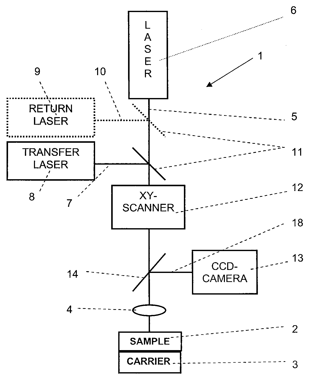
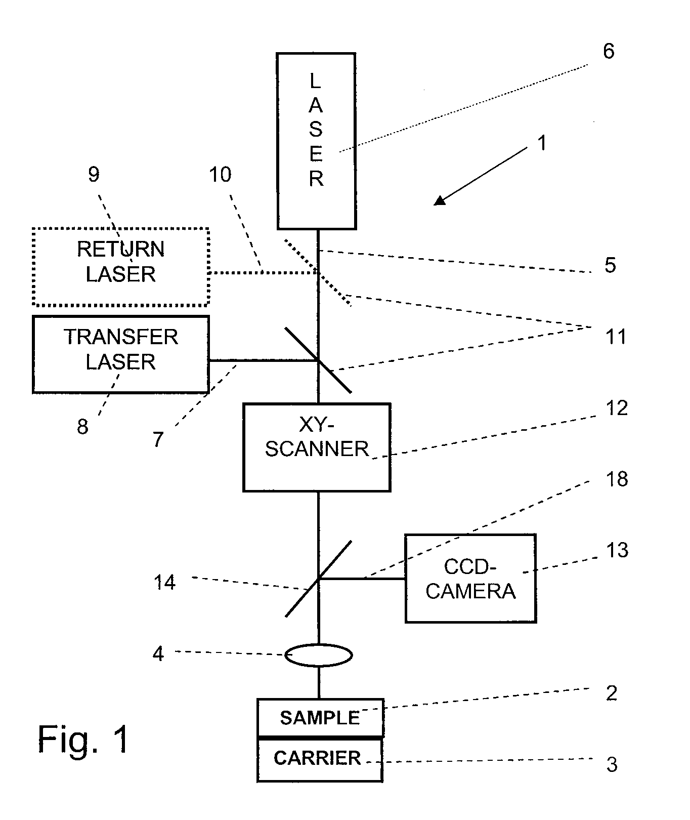
[0046]Referring now in greater detail to the drawings, the fluorescence microscope 1 depicted in FIG. 1 is used for three-dimensionally imaging a structure in a sample 2. The sample 2 is arranged on a sample carrier 3 suitable for displacing the sample 2 in the axial direction of an objective 4. The objective4 is used for focussing both an optical excitation signal 5 coming from an excitation laser 6 and an optical transfer signal 7 coming from a transfer laser 8 into a common focal spot within the sample 2. As the excitation signal 5 and the transfer signal 7 may have the same wavelength in the method of the present invention, the additional transfer laser 8 is optional. Further, a return laser 9 supplying an optional return signal 10 which is focussed in the pupil of the objective 4 may be provided. Dichroitic mirrors 11 are used to combine any optical signals 5, 7, and 10 onto one common optical axis. A xy-scanner laterally shifts the common optical axis of the optical signals 5,...


PUM


Abstract

For imaging a structure in a sample with three-dimensional spatial resolution, a fluorophore is selected which is transferable by means of an optical transfer signal out of a first into a second photochromic state having specific fluorescence properties, and which displays a return rate back into the first photochromic state. The structure is labeled with the fluorophore. Via a common objective, the sample with the labeled structure is subjected both to the optical transfer signal in a spatially limited transfer-volume, and to an optical excitation signal exciting a portion of the fluorophore being in its second photochromic state for fluorescence in a spatially limited excitation-volume, the transfer-volume and the excitation-volume having a common centre of maximum intensity of the transfer signal and of the excitation signal, and a decrease of intensity of the transfer signal with the distance to the common centre of maximum intensity being substantially stronger than any decrease of the effective return rate of the fluorophore. Fluorescence light emitted by the excited fluorophore is detected. The common centre of maximum intensity is shifted with regard to the sample; and the steps of subjecting and detecting are repeated.

Description

CROSS REFERENCE TO RELATED APPLICATIONS[0001]This application claims priority to co-pending European Patent Application No. EP 08 006 232.6 entitled “Method of fluorescence-microscopically imaging a structure in a sample with high three-dimensional spatial resolution”, filed Mar. 31, 2008.FIELD OF THE INVENTION[0002]The invention relates to a method of fluorescence-microscopically imaging a structure in a sample with three-dimensional spatial resolution. Particularly, the invention relates to a method of imaging a structure in a sample comprising the steps of labelling the structure with a fluorophore; subjecting the sample in a spatially limited excitation-volume to an optical excitation signal exciting a portion of the fluorophore located in the excitation-volume for fluorescence; detecting fluorescence light emitted by the excited fluorophore located in and about a centre of maximum intensity of the excitation signal; shifting the centre of maximum intensity of the excitation sig...

Claims


Application Information

Patent Timeline
Patent Type & Authority Applications(United States)
IPC IPC(8): G01J1/58
CPCG01N21/6458G01N21/6428
Inventor ENGELHARDT, JOHANNLANG, MARIONHELL, STEFAN
Owner MAX PLANCK GESELLSCHAFT ZUR FOERDERUNG DER WISSENSCHAFTEN EV
Why Eureka
Try Eureka