Pulse-position-modulated vehicular alternator voltage regulator with dual AC-feedback networks, controlled "OFF" period and low inserted electrical noise

a voltage regulator and pulse position technology, applied in the direction of electric generator control, dynamo-electric converter control, control system, etc., can solve the problems of increasing the level of electrical noise introduced into the electrical system of the vehicle, not without limitations, and noticeable (and objectionable) voltage/current low frequency fluctuation at the alternator output, etc., to achieve tight voltage regulation, enhance performance, and improve performance

Inactive Publication Date: 2009-10-01
BARTOL LUIS E +1
View PDF0 Cites 0 Cited by
  • Summary
  • Abstract
  • Description
  • Claims
  • Application Information

AI Technical Summary

Benefits of technology

[0021]First, a power stage of a Frequency-On-Demand type voltage regulator is configured as a resettable monostable multivibrator that provides: (1) a stable time-base that serves as an internal “OFF”-period reference, (2) short-circuit protection to the output power transistor as taught in U.S. Pat. Nos. 5,325,044 and 5,744,941; and (3) a pulse train with sharply defined “ON” and “OFF” transitions as the result of the interaction between the Output and Input Sections of the power stage through a first AC Feedback Network; and (4) voltage-reference loss protection. Additionally, the “ON” and “OFF” regulating signal transitions are rounded-off as is taught in U.S. Pat. No. 6,667,739 to reduce inserted electrical noise.
[0023]Of the first and the second elements above, the second AC feedback network constitutes the key element in rendering a Frequency-On-Demand voltage regulator that complies with the objects of the present invention. Moreover, this new, second, feedback network produces an added bonus: it also enables an exceptionally tight voltage regulation. The benefits accrued by the incorporation of the second AC feedback enhance the performance of those prior art voltage regulators referenced as FIGS. 1 and 2 (as respectively show voltage regulators in accordance with U.S. Pat. Nos. 5,325,044 and 5,744,941), without interfering with, or decreasing the efficacy of, any of the valuable features incorporated in these prior art regulators. For example, the short-circuit protection feature of the previous voltage regulators remains intact in the new proposed designs of the present invention. Also, the voltage-reference loss feature of the previous regulators is now fully implemented by the second AC feedback network, which serves to trigger a safe self-oscillating mode upon loss of the reference voltage (“B+” in FIG. 3 and “NEG” in FIG. 4).
[0024]The modifications in accordance with the present invention that are required to so improve performance—namely, the second feedback network—do not significantly affect the cost, reliability and / or complexity of the current Frequency-On-Demand voltage regulators.
[0027]The improvement to the Frequency-On-Demand type voltage regulator preferably further realizes a stable internal time reference of the resettable monostable multivibrator output stage. This reference serves to maintain “OFF” the output stage for a fixed time interval, and current through a field winding of an alternator connected to the output stage. By this structure, and this operation, voltage / current fluctuations both at no load and at near full load on the alternator, said fluctuations known in the trade as “jitter”, are substantially eliminated.

Problems solved by technology

As alternators became larger because of higher use of electrical power in vehicles, the response time due to very large field inductances and currents involved became quite significant and when added to the response time of the voltage regulator itself, resulted in a noticeable (and objectionable) voltage / current low frequency fluctuation at the alternator output.
The downside of this improvement is that the ON-OFF-ON transitions of the pulse-train had to be made faster, which increased the level of electrical noise introduced into the vehicle's electrical system.
Up until recently, cost and complexity issues kept this technology available only in those applications that demanded high levels of performance.
However, it is not without limitations.
Its very reliance on a fixed frequency makes it particularly vulnerable to high electrical noise environments such as electrical vehicular systems that have temporarily lost battery connections, typically as a result of such connections becoming loose in the high-vibration environment of the modern heavy duty vehicle.
In this case, when a large electrical load is applied to the battery-less alternator, it could cause the permanent shut-off of the voltage regulator, rendering inoperable the auxiliary battery-less system.

Method used


Image

  • Pulse-position-modulated vehicular alternator voltage regulator with dual AC-feedback networks, controlled "OFF" period and low inserted electrical noise
  • Pulse-position-modulated vehicular alternator voltage regulator with dual AC-feedback networks, controlled "OFF" period and low inserted electrical noise
  • Pulse-position-modulated vehicular alternator voltage regulator with dual AC-feedback networks, controlled "OFF" period and low inserted electrical noise

Examples


Embodiment Construction

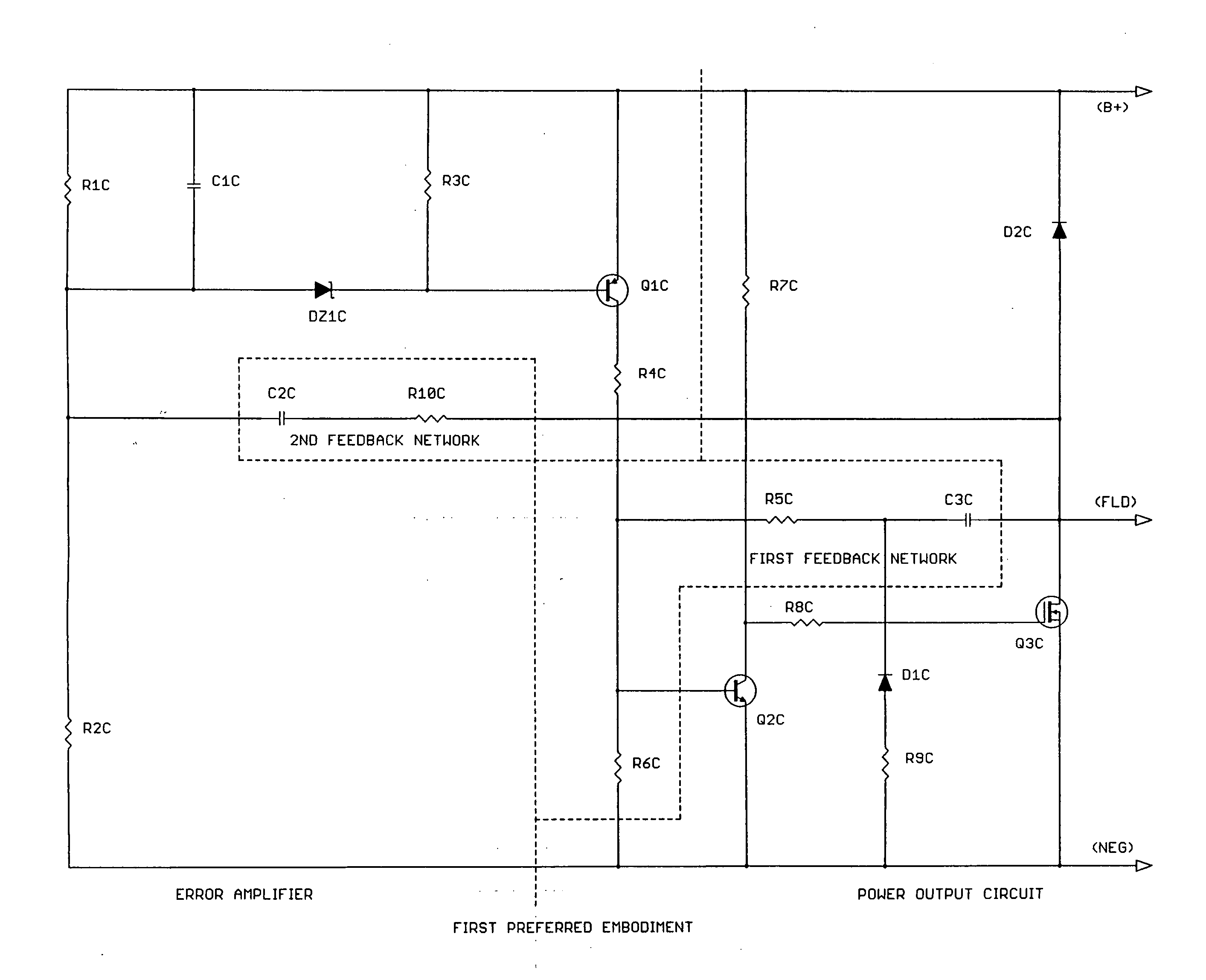
[0040]1. A functional description of a preferred first, proposed “A-type” (one end of the alternator field connected to “B+”) embodiment of the present invention referenced to the schematic drawing of FIG. 3 is as follows:

[0041]1.1 The network comprised by Q2C, R5C, R6C, R7C, R8C, R9C, D1C, D2C, C3C and Q3C is functionally a resettable, monostable multivibrator whose time constant is primarily determined by R5C, R6C and C3C. Diode D1C and resistor R9C reset capacitor C3C to a residual, well-defined reset voltage, every time power transistor Q3C goes into conduction. As taught in U.S. Pat. Nos. 5,325,044 and 5,744,941, diode D1C is the key element of the short-circuit protection function, Therefore, this short-circuit protection scheme doubles as a resettable, monostable multivibrator timer. The utilization of this built-in timer as an internal reference to make the response time of the voltage regulator independent of external variables is one of the objects of the present invention...


PUM


Abstract

A Frequency-On-Demand type voltage regulator firstly has its power output circuit configured as a resettable monostable multivibrator that provides (1) a stable time-base that serves as an internal “OFF”-period reference; preferably also with (2) short-circuit protection to the output power transistor; and (3) a pulse train with sharply defined “ON” and “OFF” transitions as the result of the interaction between the Output and Input Stages of the Power Output Circuit through a first AC Feedback Network. The “ON” and “OFF” transitions are preferably rounded-off. Secondly, yet another, second, AC feedback network is added between the Output Stage of the Power Output Circuit and the Error-Detector / Voltage Divider Stage of the Frequency-On-Demand type voltage regulator. This second feedback network provides (1) a controlled “OFF”-period synchronized with the Output Stage signal; (2) protection against loss of a reference voltage; (3) a dead band” associated with the “ON” and “OFF” periods that confers exceptional tolerance to system electrical noise; and (4) a voltage compensation feature with “flat”, “drooping” or “rising” system voltage output characteristic versus system loading.

Description

REFERENCE TO RELATED PATENTS[0001]The present patent application is related to U.S. Pat. No. 6,667,739 issued Jan. 13, 2004 for a HIGH-RELIABILITY, LOW-COST, PULSE-WIDTH-MODULATED VEHICULAR ALTERNATOR VOLTAGE REGULATOR WITH SHORT-CIRCUIT PROTECTION AND LOW INSERTED ELECTRICAL NOISE to Luis E. Bartol and Muriel Bartol, which said Luis E. Bartol and Muriel Bartol are co-inventors of the present invention.[0002]This related predecessor patent, and the present application, are in turn related to U.S. Pat. No. 5,744,941 issued Apr. 28, 1998, for a SINGLE-WIRE-CONNECTED HIGH-SENSITIVITY DUAL MODE A.C. / D.C. TURN-ON / TURN-OFF STAGE FOR AN ELECTRONIC VOLTAGE REGULATOR issued to Luis E. Bartol and German Holguin, and to U.S. Pat. No. 5,325,044 issued Jun. 28, 1994 for an ELECTRONIC VOLTAGE REGULATOR PROTECTED AGAINST FAILURE DUE TO OVERLOAD, OR DUE TO LOSS OF A REFERENCE VOLTAGE to Luis E. Bartol.[0003]The contents of the related predecessor patents are incorporated herein by reference.BACKGRO...

Claims


Application Information

Patent Timeline
Patent Type & Authority Applications(United States)
IPC IPC(8): H02P9/48
CPCH02P9/305
Inventor BARTOL, LUIS E.BARTOL, MURIEL L.
Owner BARTOL LUIS E
Why Eureka
Try Eureka