Endoscope measuring 3-d profile

a technology of endoscope and three-dimensional profile, which is applied in the field of endoscope system, can solve the problems of difficult use with a general-purpose endoscope without the 3-d measurement function, and the process of calculating the 3-dimensional profile takes time, and achieves the effect of simple construction

Inactive Publication Date: 2009-10-01
HOYA CORP
View PDF8 Cites 61 Cited by
  • Summary
  • Abstract
  • Description
  • Claims
  • Application Information

AI Technical Summary

Benefits of technology

[0007]An object of the present invention is to provide an endoscope system of simple construction that is capable of projecting a pattern freely and measuring the 3-D profile of a target instantaneously.

Problems solved by technology

However, the process of calculating a 3-D profile takes time since a conventional endoscope with 3-D measurement function is designed such that the whole of the 3-D profile is precisely measured.
Also, a conventional endoscope system with 3-D measurement function is equipped with an exclusive component such as a pattern mask, which is hard to use with a general-purpose endoscope without the 3-D measurement function.

Method used


Image

  • Endoscope measuring 3-d profile
  • Endoscope measuring 3-d profile
  • Endoscope measuring 3-d profile

Examples


first embodiment

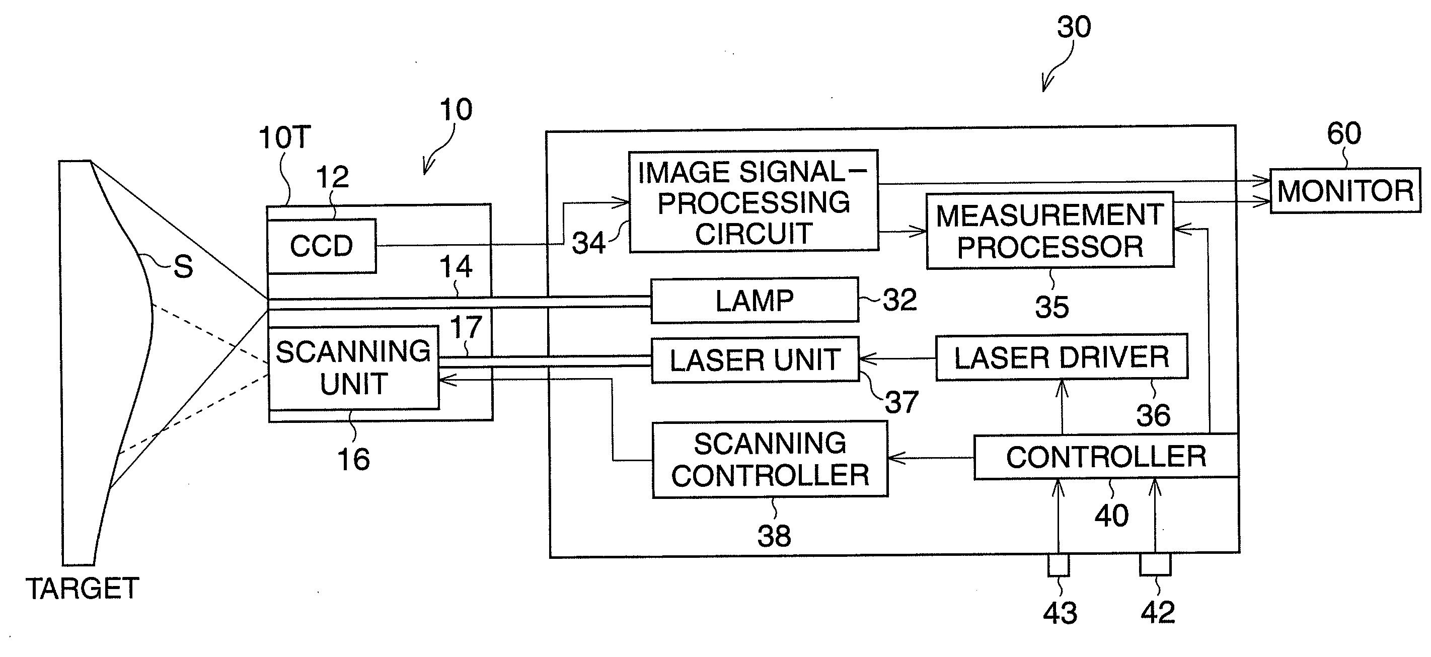
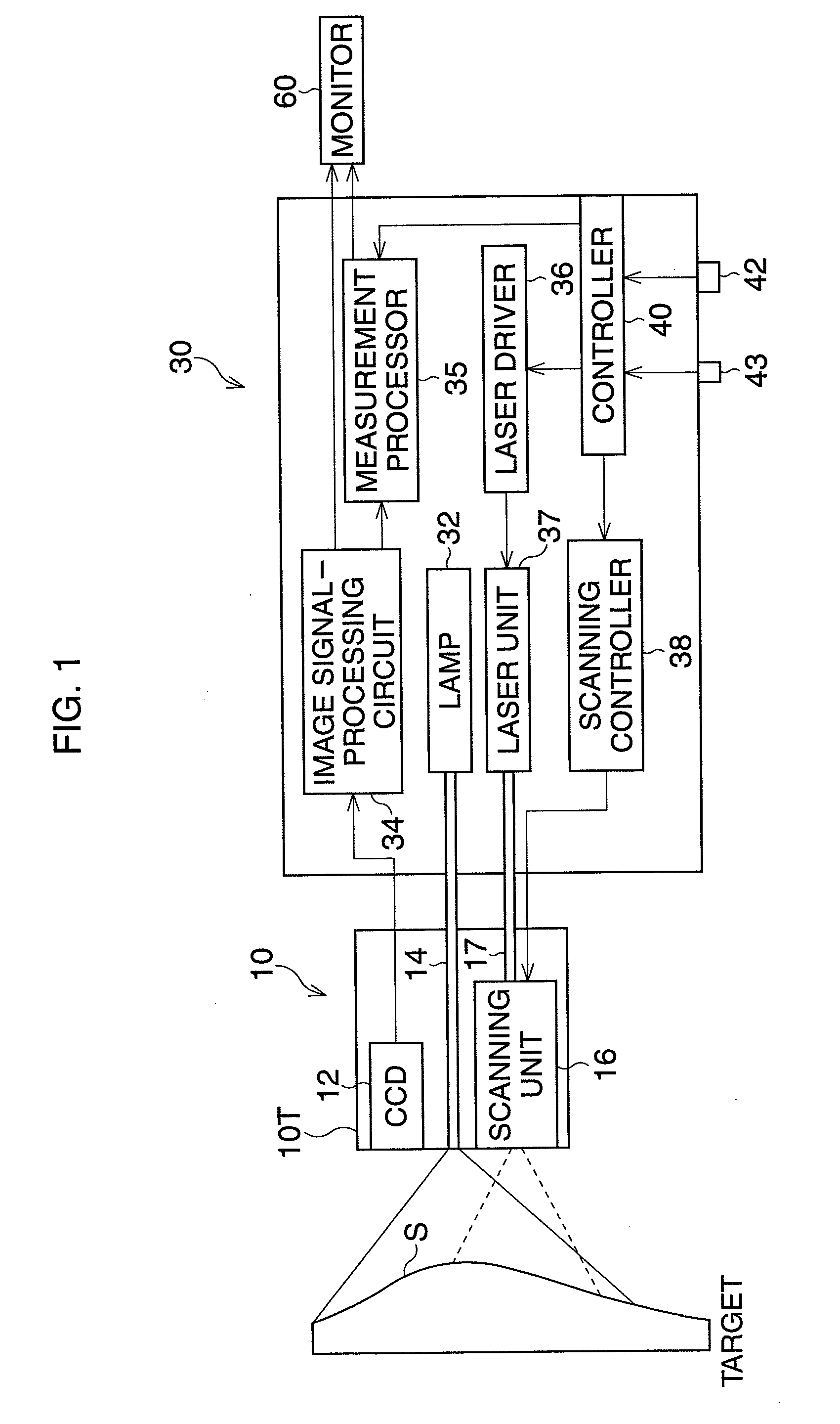
[0043]FIG. 1 is a block diagram of an endoscope system according to the

[0044]The endoscope system is equipped with a videoscope 10 having a CCD 12 and a processor 30. The endoscope 10 is detachably connected to the processor 40, and a monitor 60 and a keyboard (not shown) are also connected to the processor 40. An observation lamp 32, provided in the video processor 20, emits white light. The emitted light is delivered to the distal end 10T of the videoscope 10 by a light guide 14 composed of optic-fiber bundles. Light passing through the light guide 14 is cast from the distal end 10T of the videoscope 10 toward a target S.

[0045]Light reflected from the target S passes through an objective lens (not shown) and reaches the CCD 12, so that a subject image is formed on a light-receiving area of the CCD 12. On the light-receiving area of the CCD 12, a complementary color filter (not shown), checkered with a repeating pattern of the four color elements, Yellow (Y), Magenta (Mg), Cyan (Cy...

third embodiment

[0088]FIG. 13 is a block diagram according to the In the distal end 10′T of a videoscope 10′, an LCD shutter 19 composed of two-dimensionally arrayed LCDs is provided. The LCD shutter selectively passes or blocks light exiting from the optical fiber 17.

[0089]The controller 40 outputs control signals to an LCD controller 45 to synchronize the strobing of the LCD 19 with the scan timing of the scanning unit 16. The LCD 19 passes the emitted light when the scanning position is on a pattern, whereas the LCD 19 blocks the light when the scanning position is outside of the pattern. Note, any space modulation device (e.g., Digital Micro-mirror Device) other than the LCD shutter may optionally be used.

[0090]The fourth embodiment is explained with reference to FIG. 14. The fourth embodiment is different from the first embodiment in that an independent scanning system and a projection system are included. Other constructions are substantially the same as those of the first embodiment.

fourth embodiment

[0091]FIG. 14 is a block diagram of an endoscope system according to the

[0092]In a videoscope 100 having a CCD 112 and a light guide 114, a scanning system is not provided. Instead, a probe type scanning scope 200 is used. The thin scanning scope 200 has a single type optical fiber 220, and is connected to a projection unit 300. A videoprocessor 400 is equipped with a lamp 432, an image signal-processing circuit 434, a measurement processor 435, and a controller 440.

[0093]The projection unit 300 is equipped with a laser unit 320, laser driver 340, a scanning controller 360, and a system controller 380. When measuring 3-D information of a tissue, the scanning scope 200 is inserted into a forceps channel 110M provided in the videoscope 100. The tip portion of the optical fiber 220 is driven spirally by a scanning unit 240 provided in the distal end of the scanning scope 200. The system controller 380 controls the emission of light from the laser unit 320 in accordance with a pattern s...


PUM


Abstract

An endoscope system has a scanner, a projector, and a measurement processor. The scanner is configured to scan light that passes through an optical fiber over a target by directing the light emitted from the distal end of an endoscope. The projector is configured to project a pattern on the target by switching on and off the light during scanning. Then, the measurement processor acquires a three dimensional (3-D) profile of the target on the basis of the shape of the pattern projected on the target.

Description

BACKGROUND OF THE INVENTION[0001]1. Field of the Invention[0002]The present invention relates to an endoscope system, and in particular, it relates to a process for measuring a three-dimensional (3-D) profile of a target to be observed, such as biological tissue.[0003]2. Description of the Related Art[0004]An endoscope system with 3-D measurement function illuminates a target having a convex shape such as a cubic shape, and measures the 3-D profile of the target, or the size of the 3-D profile, on the basis of light reflected from the target. In Japanese unexamined publication JP1998-239030A, JP1998-239034A, JP1997-61132A, an endoscope system that measures a 3-D profile using a trigonometric method or a light-section method is described.[0005]The trigonometric method calculates the height of the target from the displacement between an illumination position on an optical system and a light-receiving position on a photo-detector. On the other hand, the light-section method simultaneou...

Claims


Application Information

Patent Timeline
Patent Type & Authority Applications(United States)
IPC IPC(8): H04N13/00H04N7/18
CPCA61B1/00172A61B5/1077A61B5/1076A61B5/0064A61B1/0605
Inventor TAKAHASHI, MASAOYOKOYAMA, YUKOIKEMOTO, YOSUKE
Owner HOYA CORP
Why Eureka
Try Eureka