Bonding method, bonded structure, liquid droplet discharging head, and liquid droplet discharging apparatus

a technology of liquid droplets and bonded structures, which is applied in the direction of water-setting substance layered products, adhesive processes with surface pretreatment, synthetic resin layered products, etc., can solve the problems of time-consuming bonding process, reduced bonding strength and size precision, increased bonding cost and complication of bonding process, etc., to achieve high size precision, high size precision, and strong and efficient bonding

Active Publication Date: 2009-10-01
SEIKO EPSON CORP
View PDF1 Cites 19 Cited by
  • Summary
  • Abstract
  • Description
  • Claims
  • Application Information

AI Technical Summary

Benefits of technology

[0015]An advantage of the present invention is to provide a method for bonding two base members to each other strongly and efficiently with high size precision. Another advantage of the invention is to provide a bonded structure using the bonding method, and still another advantage of the invention is to provide a liquid droplet discharging head and a liquid droplet discharging apparatus applying the bonding method.
[0016]The advantages are accomplished by following aspects and features.
[0017]A bonding method according to a first aspect of the invention includes a first process that includes plasmatizing a first gas including a raw gas containing a siloxane (Si—O) bond at a reduced-pressure atmosphere, substituting the first gas by a second gas mainly including an inert gas, and plasmatizing the second gas to form a first plasma polymerized film on at least a part of a base member so as to obtain a first bonded object including the base member and the plasma polymerized film and a second process that includes preparing a second bonded object that is to be bonded to the first bonded object and pressing the first and the second bonded objects against each other such that a surface of the first plasma polymerized film is closely contacted to a surface of the second bonded object to bond the objects together.
[0018]Thereby, the two bonded objects can be bonded to each other strongly and efficiently with high size precision.
[0019]Preferably, the second bonded object includes a second base member and a second plasma polymerized film that is same as the first plasma-polymerized film and formed on the second base member, and in the second process, the first and the second bonded objects are pressed against each other such that the first and the second plasma polymerized films are closely contacted to each other.
[0020]This allows the two base members to be more strongly bonded to each other.

Problems solved by technology

However, such an adhesive-based bonding has problems such as reductions in bonding strength and size precision, and a time-consuming bonding process because of its long curing time.
Thus, cost and time for use of the primer leads to an increase in bonding cost and complication of the bonding process.
In the method, however, there are several problems as follows: (1) Materials of bonded members are restricted; (2) The bonding process requires heating at a high temperature (ranging approximately from 700 to 800° C., for example); and (3) Atmosphere during the bonding process is restricted to a reduced-pressure atmosphere.

Method used


Image

  • Bonding method, bonded structure, liquid droplet discharging head, and liquid droplet discharging apparatus
  • Bonding method, bonded structure, liquid droplet discharging head, and liquid droplet discharging apparatus
  • Bonding method, bonded structure, liquid droplet discharging head, and liquid droplet discharging apparatus

Examples


first embodiment

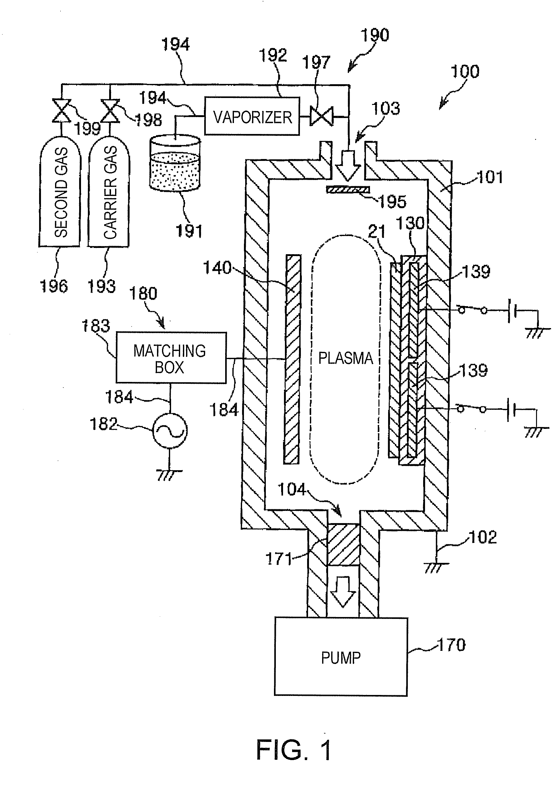
[0087]Next will be described the bonding method according to the first embodiment based on an example of the plasma polymerization apparatus 100.

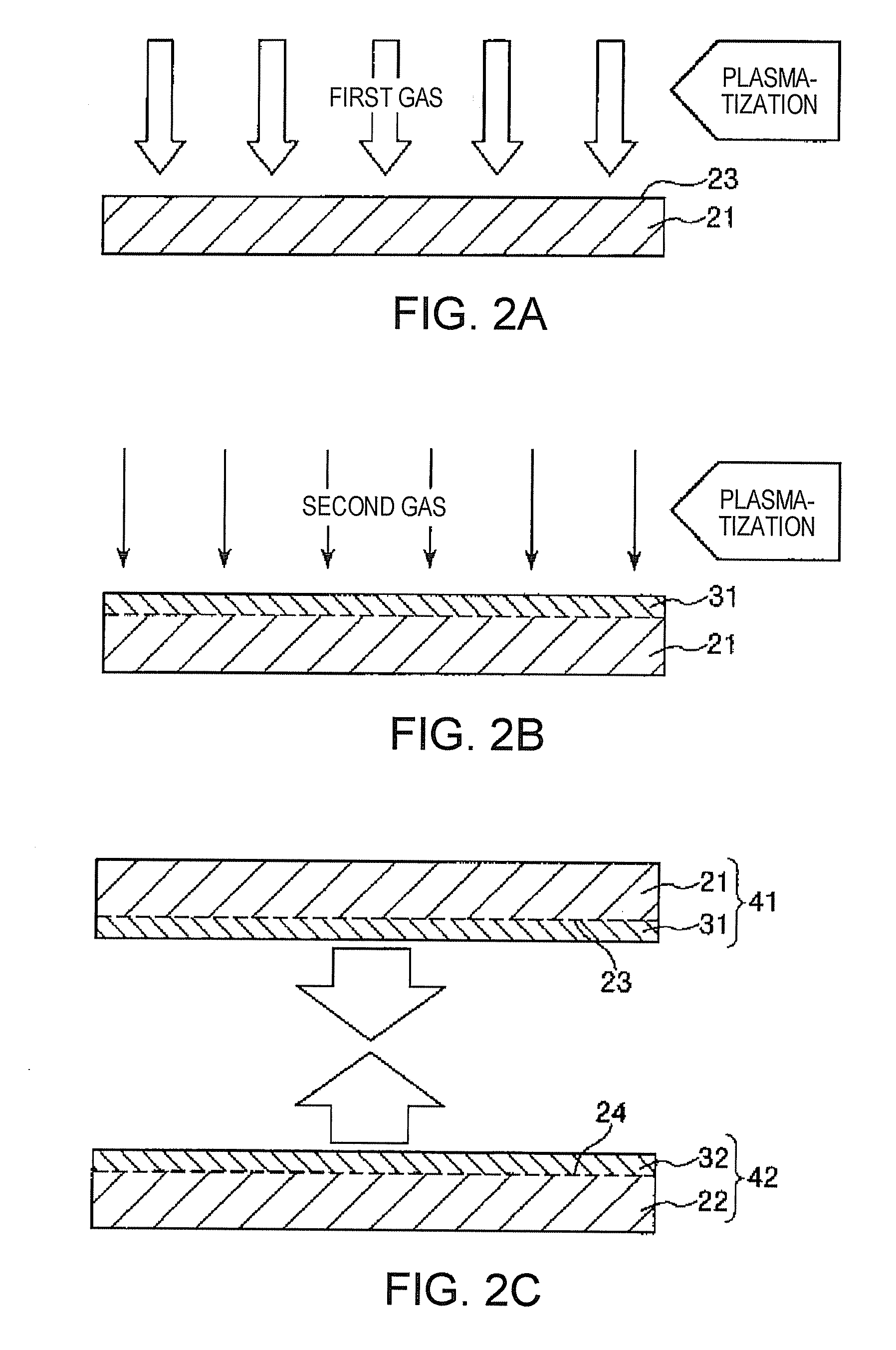
[0088]FIGS. 2A to 2C and FIGS. 3D and 3E are longitudinal sectional views for illustrating the bonding method of the first embodiment. In the description below, upper and lower sides respectively in the drawings will be referred to as “upper” and“lower”, respectively.

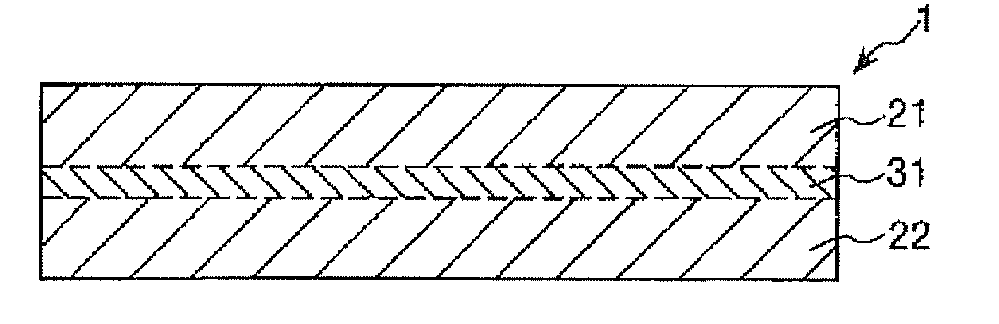
[0089]The bonding method of the first embodiment includes a first process that includes forming the plasma polymerized film 31 on the surface of the first base member 21 to obtain a first bonded object 41 and a second process that includes forming the plasma polymerized film 32, which is the same as the plasma polymerized film 31, on a surface of the second base member 22 to obtain a second bonded object 42 and bonding the first and the second bonded objects 41 and 42 to each other such that the plasma polymerized films 31 and 32 are closely contacted to each other so as to obt...

second embodiment

[0206]Next will be described a bonding method according to a second embodiment of the invention.

[0207]FIGS. 5A and 5B are longitudinal sectional views for illustrating the bonding method of the second embodiment. In a description below, upper and lower sides, respectively, in the drawings, will be referred to as “upper” and “lower”, respectively.

[0208]In the description of the bonding method of the second embodiment, points different from those in the bonding method of the first embodiment will be focused on and same points as in the first embodiment will be omitted.

[0209]The second embodiment is the same as the first embodiment excepting that the plasma polymerized film 32 of the second bonded object 42 is omitted in the second embodiment.

[0210]Specifically, in the bonding method of the second embodiment, as shown in FIG. 5A, the second base member 22 is used as the second bonded object 42. Then, as shown in FIG. 5B, the first and the second base members 21 and 22 are bonded togeth...

example 1

[0266]First, as a first base member and a second base member, respectively, there were prepared a monocrystalline silicon substrate and a glass substrate, respectively, each having a length of 20 mm, a width of 20 mm, and an average thickness of 1 mm.

[0267]Next, the monocrystalline silicon substrate and the glass substrate each were stored in the chamber 101 of the plasma polymerization apparatus 100 shown in FIG. 1 to perform surface treatment using oxygen plasma.

[0268]Then, a plasma polymerized film having an average thickness of 200 nm was formed on a surface of each substrate subjected to the surface treatment. Conditions for film-formation were as follows:

[0269]Film-Formation Conditions

[0270]First Gas (The first gas was slowly substituted by the second gas during a film-formation process.)

[0271]Composition of raw gas: octamethyltrisiloxane

[0272]Flow rate of raw gas: 50 sccm

[0273]Composition of carrier gas: argon

[0274]Flow rate of carrier gas: 100 sccm

[0275]Pressure upon introdu...


PUM

PropertyMeasurementUnit
pressureaaaaaaaaaa
thicknessaaaaaaaaaa
temperatureaaaaaaaaaa

Abstract

A bonding method includes a first process that includes plasmatizing a first gas including a raw gas containing a siloxane (Si—O) bond at a reduced-pressure atmosphere, substituting the first gas by a second gas mainly including an inert gas, and plasmatizing the second gas to form a first plasma polymerized film on at least a part of a base member so as to obtain a first bonded object including the base member and the plasma polymerized film and a second process that includes preparing a second bonded object that is to be bonded to the first bonded object and pressing the first and the second bonded objects against each other such that a surface of the first plasma polymerized film is closely contacted to a surface of the second bonded object to bond the objects together.

Description

[0001]The entire disclosure of Japanese Patent Application No. 2008-095472, filed Apr. 1, 2008 is expressly incorporated by reference herein.BACKGROUND[0002]1. Technical Field[0003]The present invention relates to a bonding method, a bonded structure, a liquid droplet discharging head, and a liquid droplet discharging apparatus.[0004]2. Related Art[0005]Conventionally, two base members are bonded (adhesively bonded) together by an adhesive such as an epoxy, urethane, or silicon adhesive.[0006]For example, a liquid droplet discharging head (an inkjet recording head) incorporated in inkjet printers is constructed by bonding together components made of different materials such as resin, metal, or silicon with an adhesive,[0007]In this case, a liquid or paste-adhesive is applied to a bonded surface of each component to bond the components to each other via the adhesive applied. Then, heat or light is applied to cure the adhesive, thereby achieving bonding between the components.[0008]Ho...

Claims


Application Information

Patent Timeline
Patent Type & Authority Applications(United States)
IPC IPC(8): B32B17/10B32B27/06B29C65/00B41J2/14
CPCB29C66/001C09J5/02B29C66/82661B29K2021/00B29K2021/006B29K2023/00B29K2023/06B29K2023/083B29K2023/086B29K2023/12B29K2025/00B29K2027/06B29K2027/08B29K2027/12B29K2027/16B29K2029/04B29K2033/12B29K2055/02B29K2059/00B29K2067/00B29K2067/006B29K2069/00B29K2071/00B29K2071/12B29K2075/00B29K2077/00B29K2077/10B29K2079/08B29K2079/085B29K2081/04B29K2081/06B29K2083/00B29K2096/005B29K2105/0079B29K2995/0039B29L2031/767B41J2/161B41J2/1623B29C66/02B29C66/1122B29C66/7392B29C66/73921B29C66/7394B29C66/73941B29C66/45B29C66/73111B29C66/73112B29C65/02B29C66/71B29C66/72325B29C66/723B29C66/72321B29C66/72323B29C66/73161Y10T428/31667Y10T428/31645B29K2075/02B29K2067/003B29K2063/00B29K2061/04B29K2033/08B29K2027/18B29K2025/06B29K2023/38B29K2023/18B29K2023/16B29K2019/00B29K2009/06B29K2009/00
Inventor MATSUO, YASUHIDE
Owner SEIKO EPSON CORP
Why Eureka
Try Eureka