
Drainage water-treating method and drainage water-treating apparatus

a technology of draining water and drainage water, applied in the direction of multi-stage water/sewage treatment, filtration separation, separation process, etc., can solve problems such as harm to the ecosystem, and achieve the effect of effective decomposition and effective decomposition

Inactive Publication Date: 2009-10-08
SHARP KK
View PDF31 Cites 4 Cited by
  • Summary
  • Abstract
  • Description
  • Claims
  • Application Information

AI Technical Summary

Benefits of technology

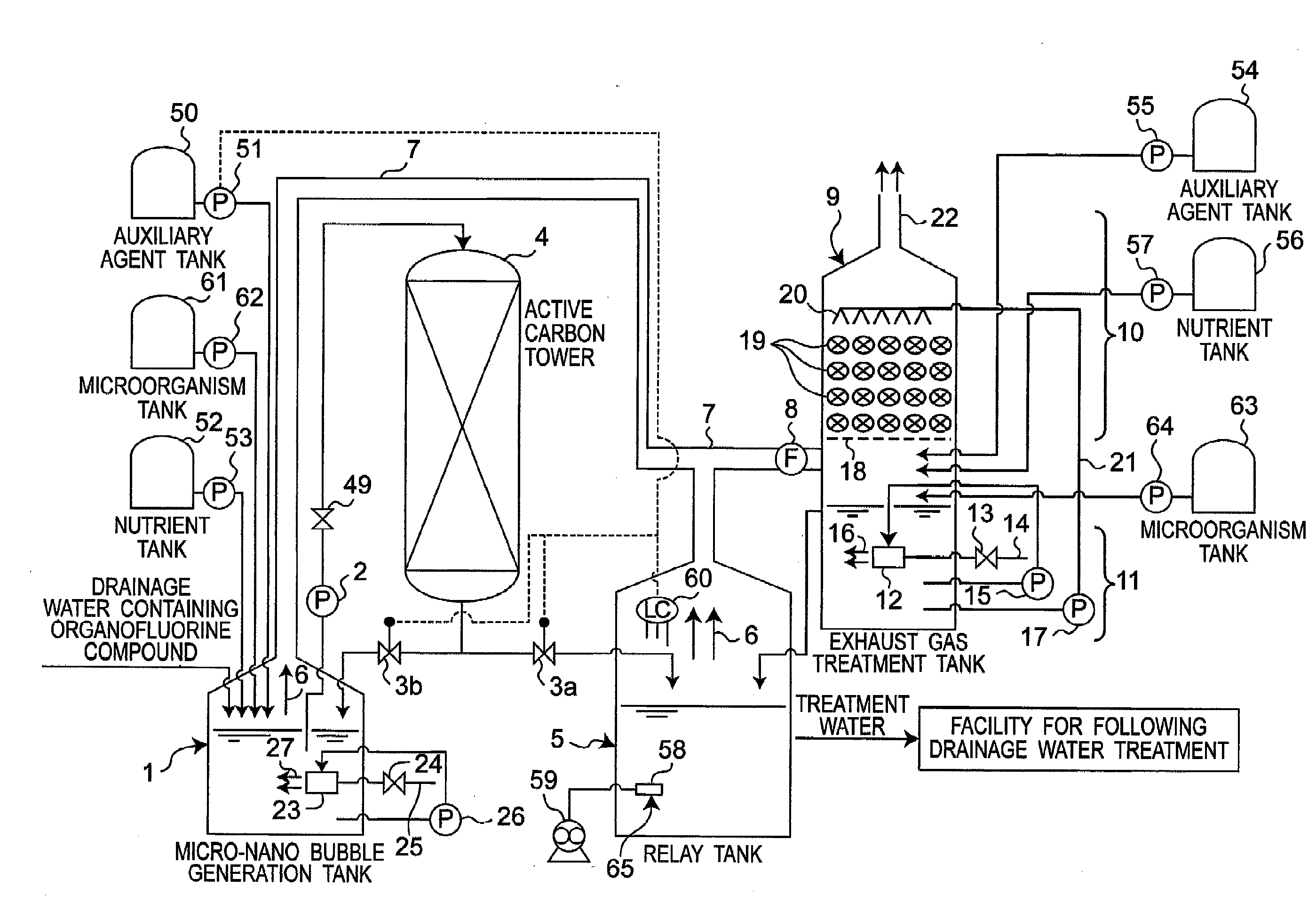
[0078]According to the drainage water-treating method of the invention, persistent organofluorine compounds can be effectively decomposed with microorganisms. This is because the microorganisms, the auxiliary agent for micro-nano bubble generation and the nutrient as well as the micro-nano bubbles are added to drainage water containing organofluorine compounds so as to produce treatment water in the micro-nano bubble generation tank, and then the treatment water is fed to the active carbon tower filled with active carbon so as to decompose the organofluorine compounds in the treatment water with use of the microorganisms.
[0079]According to the drainage water-treating apparatus of the invention, persistent organofluorine compounds can be effectively decomposed with microorganisms. This is because the drainage water-treating apparatus includes the micro-nano bubble generation tank, the microorganism tank, the auxiliary agent tank, the nutrient tank, and the active carbon tower, so that the drainage water containing organofluorine compounds is introduced into the micro-nano bubble generation tank, wherein the microorganisms, the auxiliary agent for micro-nano bubble generation and the nutrient as well as the micro-nano bubbles are added to the drainage water so as to produce treatment water, and then the treatment water is fed to the active carbon tower so as to decompose the organofluorine compounds in the treatment water with use of the microorganisms.

Problems solved by technology

The organofluorine compounds, for example, perfluorooctane sulfonate (PFOS) and perfluorooctanoate (PFOA) are hardly decomposed in the ecosystem, so that there have been concerns about harmful influence to the ecosystem.

Method used


Image

  • Drainage water-treating method and drainage water-treating apparatus
  • Drainage water-treating method and drainage water-treating apparatus
  • Drainage water-treating method and drainage water-treating apparatus

Examples


first embodiment

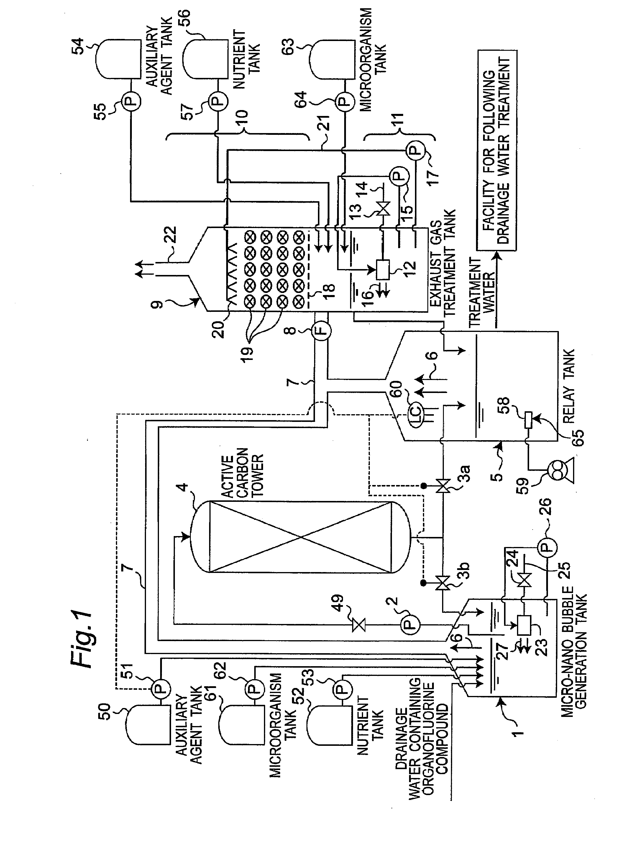
[0088]FIG. 1 shows a schematic view of a drainage water-treating apparatus in the first embodiment of the present invention. The drainage water-treating apparatus has a micro-nano bubble generation tank 1 for housing a micro-nano bubble generator 23, a microorganism tank 61 for storing microorganisms, an auxiliary agent tank 50 for storing an auxiliary agent for micro-nano bubble generation, a nutrient tank 52 for storing a nutrient, and an active carbon tower 4 filled with active carbon. The micro-nano bubble generation tank 1 is connected to the microorganism tank 61, the auxiliary agent tank 50, the nutrient tank 52 and the active carbon tower 4.

[0089]Drainage water containing organofluorine compounds is introduced into the micro-nano bubble generation tank 1. Then, the microorganisms from the microorganism tank 61, the auxiliary agent for micro-nano bubble generation from the auxiliary agent tank 61 and the nutrient from the nutrient tank 52 are added to the drainage water. The ...

second embodiment

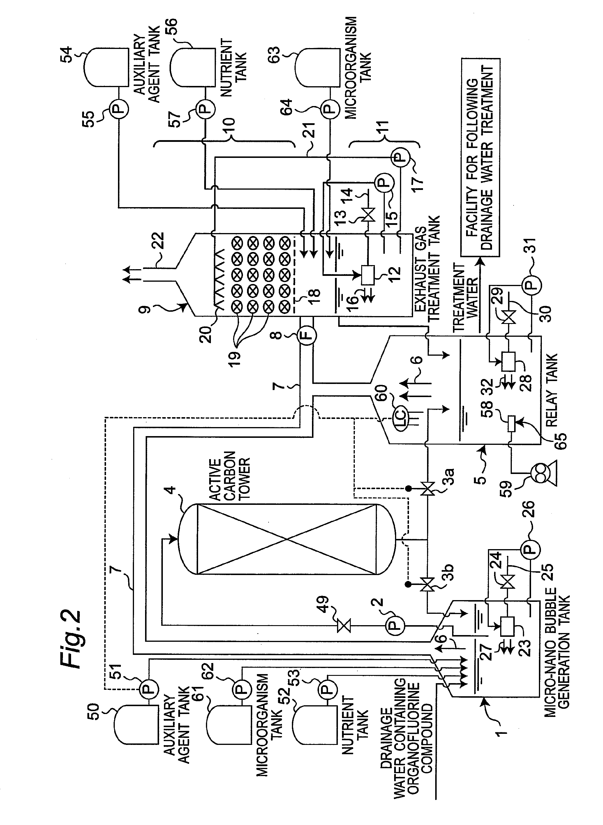
[0145]FIG. 2 shows a drainage water-treating apparatus in the second embodiment of the invention. The second embodiment is different from the first embodiment shown in FIG. 1 in the point that a micro-nano bubble generator 28 is housed in the relay tank 5. In the second embodiment, component members identical to those in the first embodiment are designated by identical reference numerals, and the explanation thereof is omitted.

[0146]The micro-nano bubble generator 28 has the same structure as the micro-nano bubble generator 23 in the first embodiment shown in FIG. 1. Therefore, the explanation thereof is omitted.

[0147]The micro-nano bubble generator 28 is connected to an air suction pipe 30. The air suction pipe 30 is connected to a valve 29 for adjusting the air suction amount. The micro-nano bubble generator 28 is connected to a circulating pump 31 for feeding the water in the relay tank 5 to the micro-nano bubble generator 28.

[0148]The micro-nano bubble generator 28 is fed with t...

third embodiment

[0155]FIG. 3 shows a drainage water-treating apparatus in the third embodiment of the invention. The third embodiment is different from the first embodiment shown in FIG. 1 in the point that a string-shaped polyvinylidene chloride filler 33, as a filler, is housed in the micro-nano bubble generation tank 1. Further, the treatment water separated from the relay tank 5 is treated with chelating resin in a chelating resin tower. In the third embodiment, component members identical to those in the first embodiment are designated by identical reference numerals, and the explanation thereof is omitted.

[0156]Since the string-shaped polyvinylidene chloride filler 33 is housed in the micro-nano bubble generation tank 1, the microorganisms activated with the micro-nano bubbles can be fixed to and propagated on the string-shaped polyvinylidene chloride filler 33. Moreover, activated microorganisms can be cultivated at high concentration on the string-shaped polyvinylidene chloride filler 33, a...


PUM

PropertyMeasurementUnit
Shapeaaaaaaaaaa

Abstract

Drainage water containing organofluorine compounds is introduced into a micro-nano-babble generation tank (1) wherein microorganisms from a microorganism tank (61), a micro-nano bubble auxiliary agent from an auxiliary agent tank (50), a nutrient from a nutrient tank (52) and micro-nano-babbles generated by a micro-nano babble generator (23) are added to the drainage water so as to produce treatment water. The treatment water is fed from the micro-nano babble generation tank (1) to an active carbon tower (4) wherein the organofluorine compounds contained in the treatment water are decomposed with the microorganisms.

Description

TECHNICAL FIELD[0001]The present invention relates to a drainage water-treating method and a drainage water-treating apparatus for use, for example, not only in semiconductor plants and liquid crystal plants but also in plants for producing or using organofluorine compounds.BACKGROUND ART[0002]Organofluorine compounds are chemically stable substances. The organofluorine compounds, in particular, have good properties in terms of heat resistance and chemical resistance. Therefore, the organofluorine compounds are used as surfactants and the like.[0003]However, the organofluorine compounds are chemically stable substances, and therefore hardly decomposed with microorganisms. The organofluorine compounds, for example, perfluorooctane sulfonate (PFOS) and perfluorooctanoate (PFOA) are hardly decomposed in the ecosystem, so that there have been concerns about harmful influence to the ecosystem. Heat decomposition of PFOS or PFOA requires high temperature of about 1000° C. or more due to t...

Claims


Application Information

Patent Timeline
IPC IPC(8): C02F9/14
CPCB01D53/44C02F2305/08B01D53/84B01D2257/2066B82Y30/00C02F1/20C02F1/283C02F3/10C02F3/20C02F3/348C02F2101/36C02F2209/003C02F2209/42C02F2303/26C02F2305/06B01D53/78Y02W10/10Y02A50/20C02F3/106
Inventor YAMASAKI, KAZUYUKISAKATA, KAZUYUKICHUHJOH, KAZUMIKATAOKA, MASAKI
Owner SHARP KK
Learn More