Lock detection circuit for phase locked loop

a detection circuit and phase lock technology, applied in the field of phase lock detectors, can solve the problems of reducing system responsiveness, affecting the overall timing performance, and introducing undesirable phase match/mismatch information propagation

Inactive Publication Date: 2009-10-08
NORTH STAR INNOVATIONS
View PDF11 Cites 36 Cited by
  • Summary
  • Abstract
  • Description
  • Claims
  • Application Information

AI Technical Summary

Problems solved by technology

In addition, delays in generating the status signals can affect the overall timing performance of the PLL, to the extent that a lock detector can introduce propagation delays which contribute to reduced system responsiveness.
Synchronizing the compa

Method used


Image

  • Lock detection circuit for phase locked loop
  • Lock detection circuit for phase locked loop
  • Lock detection circuit for phase locked loop

Examples


Embodiment Construction

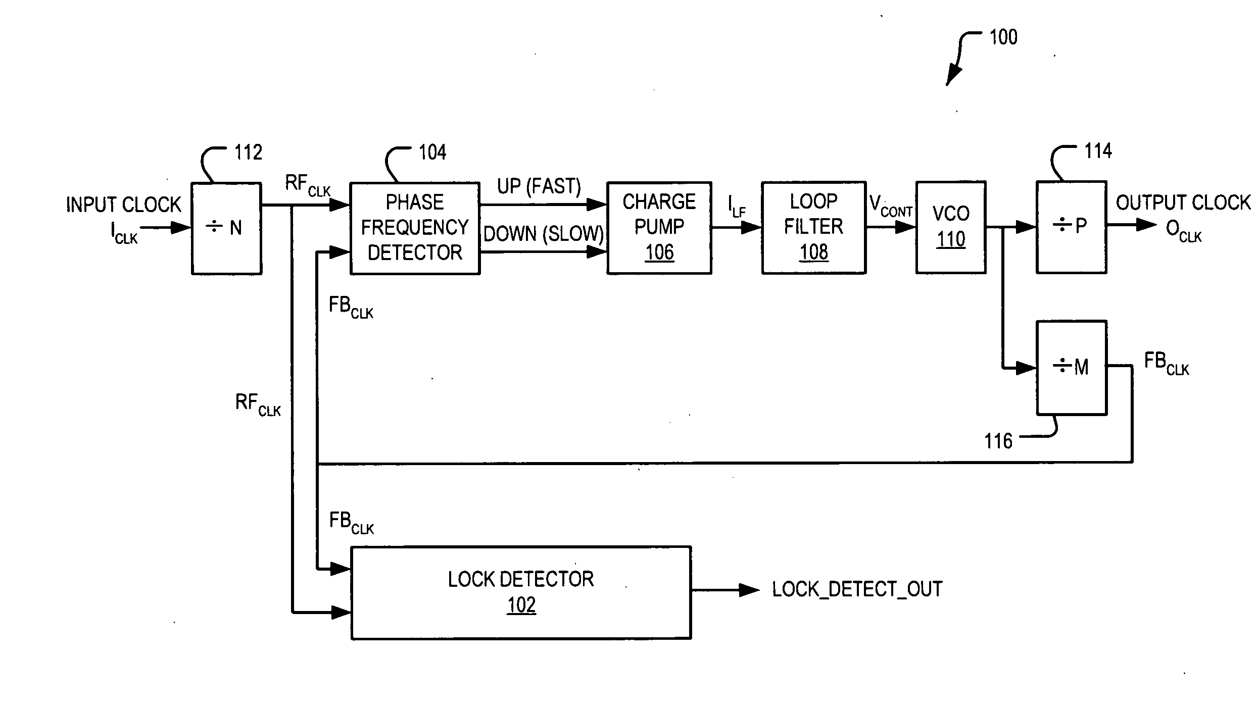
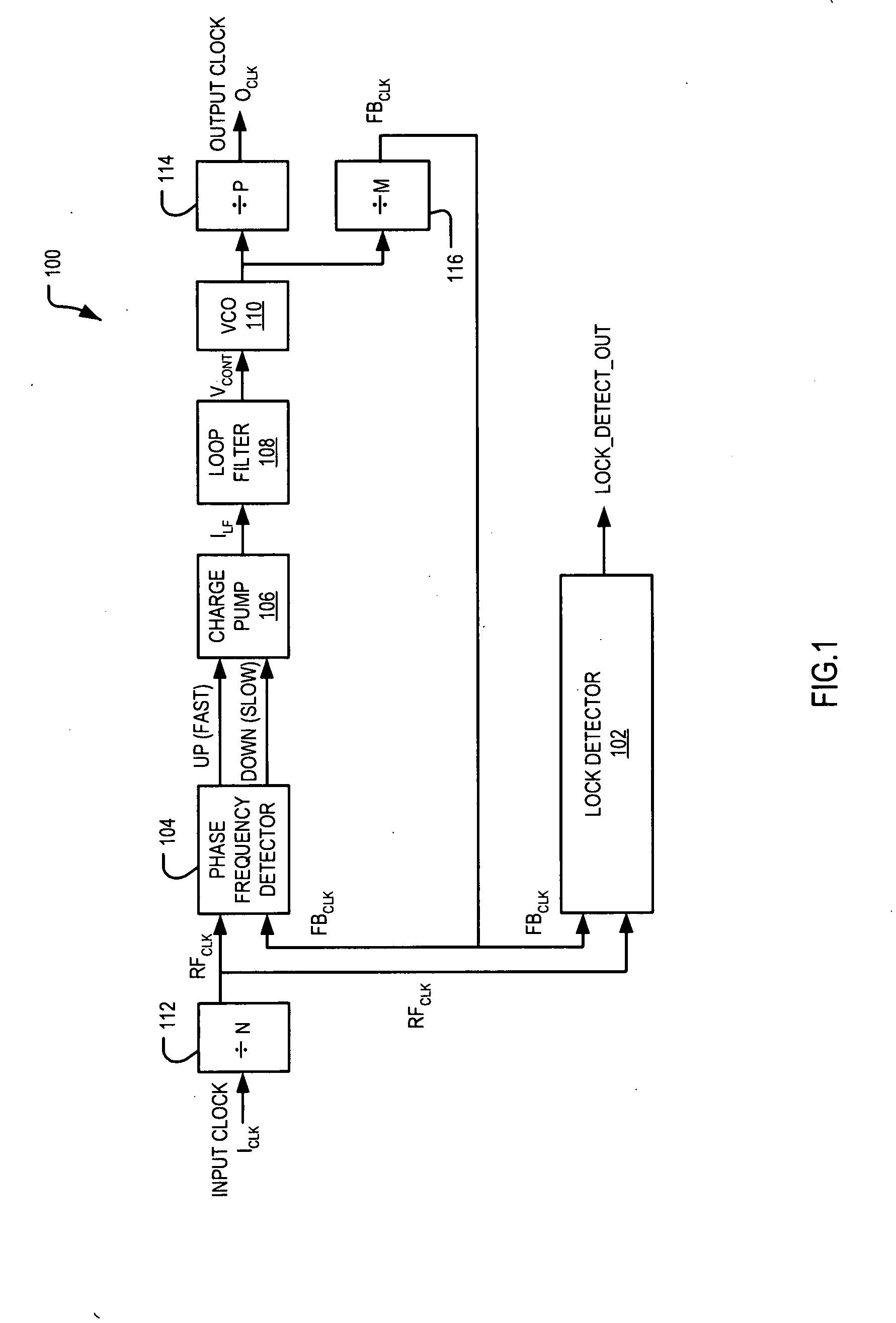
[0022]The following description describes an embodiment in relation to a lock detector for incorporating in a digital phase locked loop circuit. However, it will be appreciated that other embodiments may be used for other applications that require an indication of the extent to which the phase and frequency of two signals are synchronized.

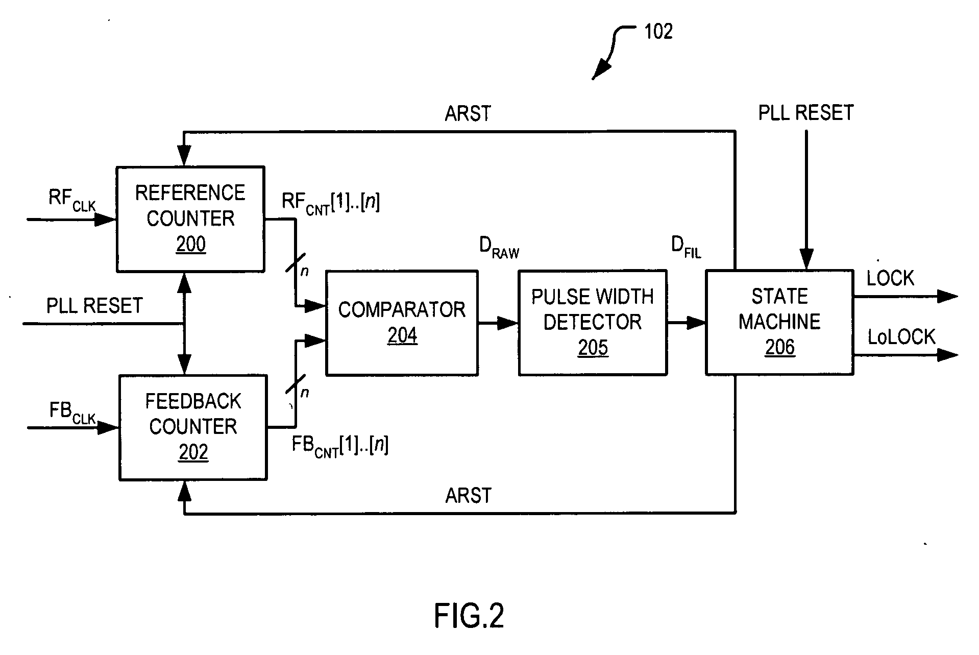
[0023]The present invention provides a lock detector circuit for detecting a lock condition between a reference signal and a feedback signal that includes a first counter outputting a first counter value indicative of a number of clock cycles of the reference signal, and a second counter outputting a second counter value indicative of a number of clock cycles of the feedback signal. An asynchronous comparator receives the first and second counter values and provides an output signal having a pulse width that is proportional to the difference between the first and second counter values. A pulse width detector receives the comparator output signal an...


PUM


Abstract

A lock detector circuit for detecting a lock condition between a reference signal and a feedback signal includes a first counter for outputting a first counter value indicative of a number of clock cycles of the reference signal, and a second counter for outputting a second counter value indicative of a number of clock cycles of the feedback signal. An asynchronous comparator receives the first and second counter values and provides an output signal having a pulse width that is proportional to the difference between the first and second counter values. A pulse width detector receives the comparator output signal and produces an output signal that is indicative of the relationship between the pulse width of the comparator output signal and a predetermined threshold value. A state machine controls the state of at least one lock indication signal according to the pulse width detector output signal.

Description

BACKGROUND OF THE INVENTION[0001]The present invention relates to phase locked loops (PLLs) and, in particular, to lock detectors for detecting when the frequency and phase of an output clock signal generated by the PLL matches that of an input clock signal.[0002]A Phase Locked Loop (PLL) is a control system that provides an output signal which is phase and frequency synchronized with an input signal. PLL circuits are used in numerous circuit applications, such as frequency synthesizers, clock generation, clock recovery and the like. A PLL may be implemented in either a digital or analog form. However, PLLs are often implemented as Silicon on Chip type devices (SoCs) that include on-chip clocks for generating the various signals. An integrated PLL on the chip avoids the need to provide a separate clock generator circuit and thus provides improved accuracy clocks and jitter performance.[0003]Generally speaking, a PLL typically includes a phase detector and an oscillator. The phase de...

Claims


Application Information

Patent Timeline
IPC IPC(8): H03L7/095
CPCH03L7/095Y10S331/02
Inventor KATHURIA, MANANABHISHEK, KUMARCHAKRAVARTY, SUHASROOPAK, SURI
Owner NORTH STAR INNOVATIONS
Why Eureka
Try Eureka