Liquid Crystal Display Device, Backlight Source and Optical Film

a liquid crystal display and backlight source technology, applied in the field of liquid crystal display devices, backlight sources and optical films, can solve problems such as difficult manufactur

Inactive Publication Date: 2009-10-08
SONY CORP
View PDF4 Cites 5 Cited by
  • Summary
  • Abstract
  • Description
  • Claims
  • Application Information

AI Technical Summary

Benefits of technology

[0019]According to the embodiments of the present invention described above, it ...

Problems solved by technology

The sheet containing dichroic dyes disclosed in Japanese Patent Application Laid-Open No. 10-293299, however, needs to be formed...

Method used


Image

  • Liquid Crystal Display Device, Backlight Source and Optical Film
  • Liquid Crystal Display Device, Backlight Source and Optical Film
  • Liquid Crystal Display Device, Backlight Source and Optical Film

Examples


first embodiment

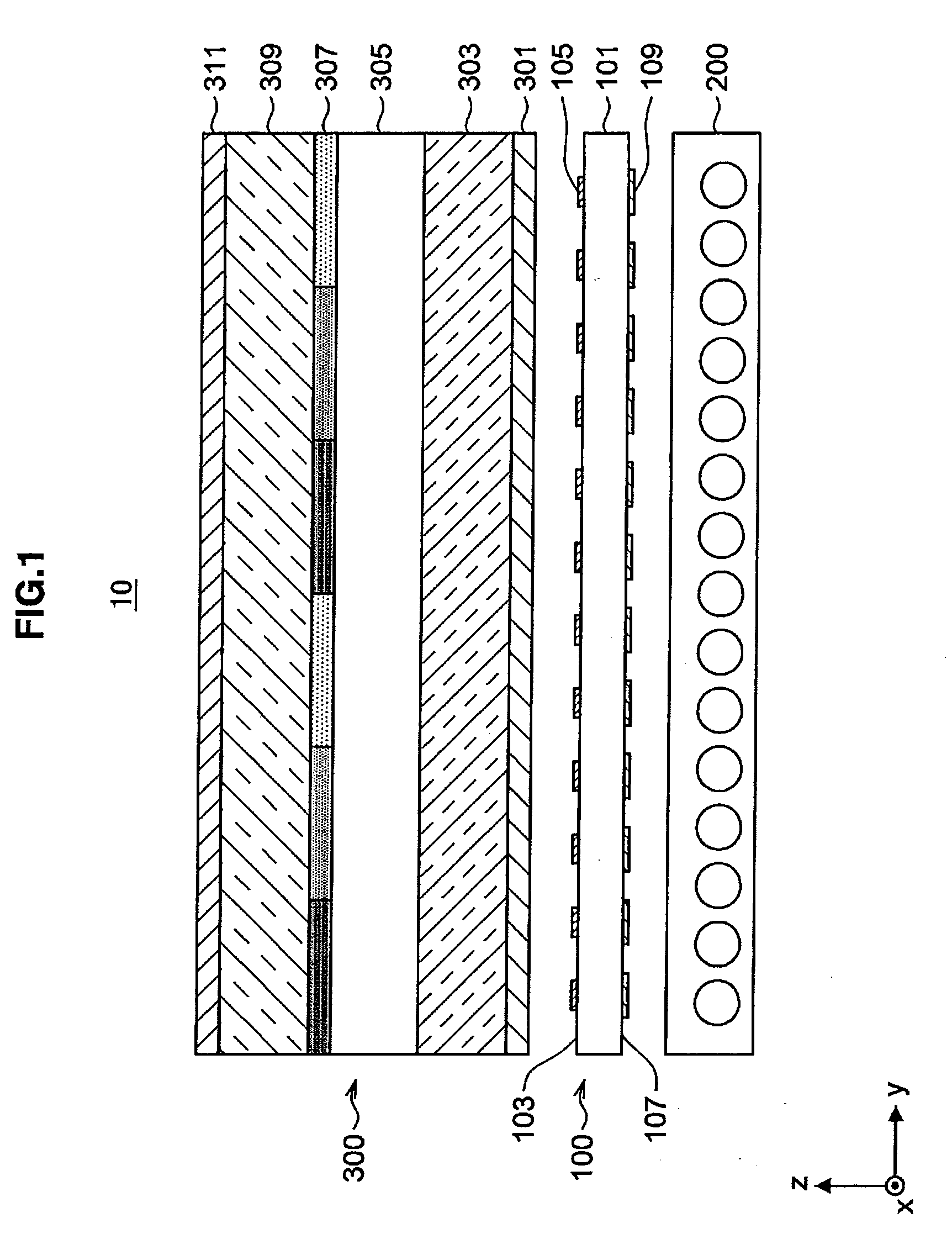
[0048]At first, referring to FIG. 1, a liquid crystal display device according to the first embodiment of the present invention will be described in detail. FIG. 1 is a view for explaining the liquid crystal display device according to the embodiment of the invention.

[0049]As shown in FIG. 1, the liquid crystal display device 10 according to the embodiment mainly includes an optical film 100, a backlight source 200, and a liquid crystal panel 300.

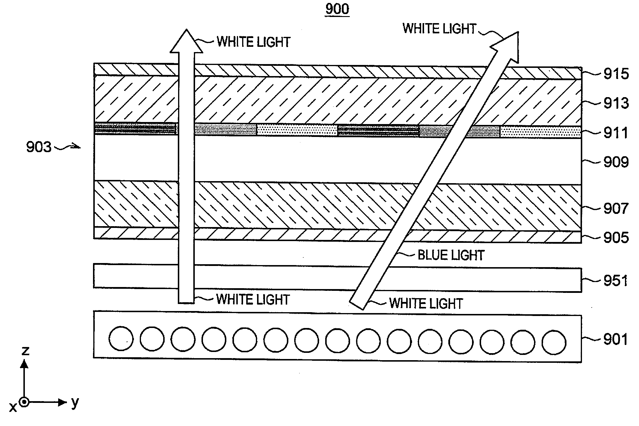
[0050]The optical film 100 is a member arranged between the backlight source 200 and the liquid crystal panel 300 described later. The optical film 100 absorbs a part of a white light supplied from the backlight source 200, and the partially absorbed white light is transmitted to the liquid crystal panel 300 arranged above the upper surface of the optical film 100. The optical film 100 will be hereinafter described in detail.

[0051]The backlight source 200 is an irradiating unit which irradiates the optical film 100 and the liquid crystal pa...

example

[0097]Next, in the liquid crystal display device 10 including the optical film 100 according to the embodiment, a simulation is performed on the front brightness and the color difference with the following conditions set. The color difference Δxy in observing the display from the polar angle 60° and the azimuth angle 45° is calculated as for the color difference.

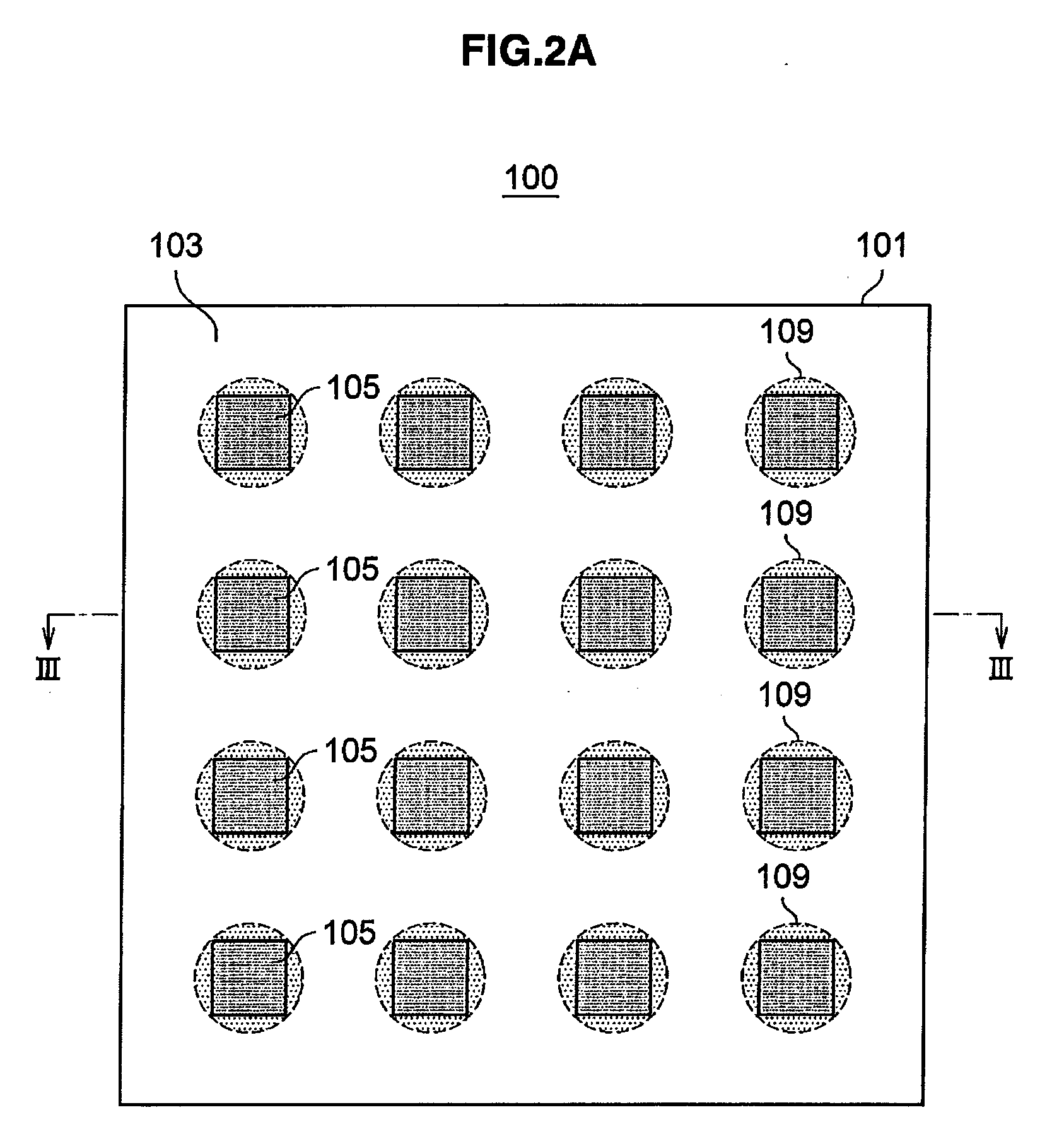
[0098]At first, assume that the blue pigment has the maximum absorption wavelength about 620 nm as shown in FIG. 9 and that the colored layer 105 and the reflective layer 109 are formed on the base material 101 having the thickness of 1000 μm under the condition shown in the Table 2. At this time, the colored layer 105 and the reflective layer 109 have substantially circle shapes and formed on the base material 101 like islands.

[0099]As the conventional example, a simulation is similarly performed on the front brightness and the color difference in the liquid crystal display device when the optical film 100 according to the ...


PUM


Abstract

A liquid crystal display device according to the present invention includes a liquid crystal panel, a backlight source provided on a rear surface of the liquid crystal panel, for irradiating the liquid crystal panel with white light, and an optical film provided between the liquid crystal panel and the backlight source, in which the optical film includes a base material which passes the white light irradiated from the backlight source, a colored layer partially provided on one surface of the base material at the side of the liquid crystal, panel, and a reflective layer provided on another surface of the base material at the side of the backlight source opposite to the colored layer, for reflecting the white light.

Description

BACKGROUND OF THE INVENTION[0001]1. Field of the Invention[0002]The present invention relates to a liquid crystal display device, a backlight source and an optical film.[0003]2. Description of the Related Art[0004]Liquid crystal display devices are in widespread use for monitors of a personal computer and a portable device and a television because of various advantages that they realize low voltage and low power consumption and they can be formed into a thinner film, downsized, or large-screen design. Such a liquid crystal display device has been provided in various modes according to the arrangement state of liquid crystals of a liquid crystal substance layer, for example, a TN (Twisted Nematic) mode, an IPS (In-Plane Switching) mode, an OCB (Optically Compensatory Bend) mode, a VA (Vertically Aligned: vertical orientation) mode. Especially a liquid crystal of the VA mode, of the above modes, has attracted attentions in recent years because of its high contrast capability.[0005]Thi...

Claims


Application Information

Patent Timeline
IPC IPC(8): G02F1/13357
CPCG02F1/133602
Inventor MAEDA, TSUYOSHIOGASAWARA, TOYOKAZU
Owner SONY CORP
Why Eureka
Try Eureka