Polarizing plate, manufacturing method of polarizing plate and liquid crystal display apparatus

a technology of polarizing plate and manufacturing method, which is applied in the direction of instruments, synthetic resin layered products, optical elements, etc., can solve the problems of reducing the front contrast of the polarizing plate, not necessarily suitable for the purpose of improving the viewing angle, and the cost of recovering solvent is very expensive to make a big load, so as to facilitate film lamination and improve the front contrast of the liquid crystal display apparatus

Inactive Publication Date: 2009-10-08
KONICA MINOLTA OPTO
View PDF4 Cites 34 Cited by
  • Summary
  • Abstract
  • Description
  • Claims
  • Application Information

AI Technical Summary

Benefits of technology

[0030]This invention can provide a polarizing plate that facilitates film lamination in the production of a polarizing plate and improves the front contrast of liquid crystal display apparatus; a process for producing such a polarizing plate; and a relevant liquid crystal display apparatus.

Problems solved by technology

For this purpose, heretofore, application of polymer film has been studied; however, cellulose triacetate (TAC) film generally has a certain phase difference value (Rt) in the thickness direction while exhibits very small phase difference value (Ro) in the intra-plane direction, and was not necessarily suitable for the purpose of viewing angle improvement of such as the above-described VA type LCD.
However, it is a present state that all of them have problems in such as contrast, dimension stability under a high temperature and high humidity condition and light leakage, improvement of which is required.
However, since a manufacturing method of cellulose resin film is generally a film forming method by a solution casting method utilizing a halogen type solvent, a cost to recover the solvent is very expensive to make a big load.
However, since tinting of film is easily caused due to a repeated thermal record when film prepared by a melt-casting method is subjected to heat stretching in the width direction, decrease of front contrast of the polarizing plate will be induced.
At the same time, decomposition of a melt substance is caused by repeating a thermal record to deteriorate smoothness of film, resulting in a problem of film lamination property at the time of manufacturing of a polarizing plate.
Further, since more thermal load is required to increase casting speed, it was difficult to increase a film production capacity.

Method used


Image

  • Polarizing plate, manufacturing method of polarizing plate and liquid crystal display apparatus
  • Polarizing plate, manufacturing method of polarizing plate and liquid crystal display apparatus
  • Polarizing plate, manufacturing method of polarizing plate and liquid crystal display apparatus

Examples


example 1

Preparation of Polarizing Plate Sample

[0290][Preparation of Polarizing Plate Sample 1-1]

[0291]Cellulose ester C-1 of 90 weight parts was dried in the air at 130° C. under ordinary pressure for 2 hours, and was left to be cooled. This cellulose ester was added with 10 weight parts of plastisizer P-1, 0.5 weight parts of hindered phenol compound S-1, 2 weight parts of ultraviolet absorbent V-1, against this cellulose ester, and the resulting mixture, after having been melt with heating at a melting temperature of 240° C., was melt-extrusion molded through a T-type die, followed by being stretched at 120° C. at a stretching ratio of 1.2 times in the machine direction and 1.4 times in the direction perpendicular to the machine direction. As a result, cellulose ester film sample having a layer thickness of 80 μm was prepared. Retardation value Ro and Rt were measured to be 45 nm and 135 nm, respectively, according to the following method. Similarly, cycloolefin type polymer film sample w...

example 2

Preparation of Polarizing Plate Samples 1-1′-1-20′

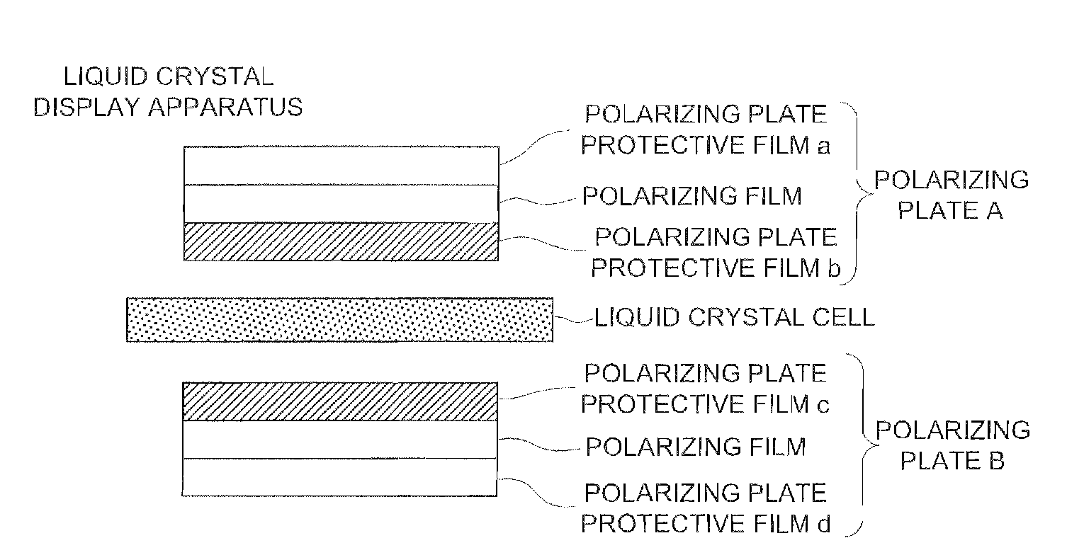
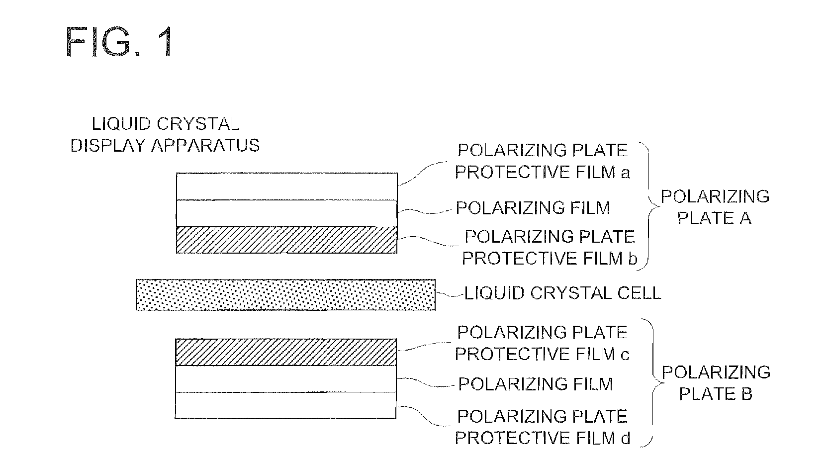
[0365]A hard-coat layer and an antireflection layer described below were provided on polymer film (polarizing plate protective film a in FIG. 1), which was employed on the viewing side of polarizing plate samples 1-1-1-20, to prepare polarizing plate samples 1-1′-1-20′.

[0366][Formation of Hard-Coat Layer]

[0367]The following hard-coat layer coating composition was filtered through a filter having a pore size of 0-4 μm and made of polypropylene to prepare a hard coat layer coating solution, which was coated on the above-described viewing side of polarizing plate protective film by use of a micro gravure coater and dried at 90° C.; then the coated layer was cured by use of an ultraviolet lamp at an illuminance at the radiation portion of 100 mW / cm2 and a irradiation quantity of 0.1 J / cm2, whereby a hard-coat layer having a dry layer thickness of 0.7 μm was formed.

[0368](Hard-Coat Layer Coating Solution)

[0369]The following each additive ...


PUM

PropertyMeasurementUnit
temperatureaaaaaaaaaa
total weightaaaaaaaaaa

Abstract

A polarizing plate arranged on at least one surface of a liquid crystal cell for use in a liquid crystal display apparatus, comprising a first polarizing plate protective film, a polarizing film, and a second polarizing plate protective film, the first polarizing plate protective film being arranged on the liquid crystal cell side with respect to a polarizing film, and the second polarizing plate protective film being arranged on the side opposite to the liquid crystal cell intervening the polarizing film, wherein the first polarizing plate protective film contains a cellulose ester and a hindered phenol compound in an amount of 0.01 to 5.0 weight % based on the total weight of the cellulose ester.

Description

TECHNICAL FIELD[0001]The present invention relates to a polarizing plate, a manufacturing method of a polarizing plate, and a liquid crystal display apparatus, and more particularly relates to a polarizing plate that facilitates film lamination in the production of a polarizing plate, improves light leakage and dimension stability under the conditions of high temperature and high humidity, and increases front contrast of a liquid crystal display apparatus; and relates to a manufacturing method of a polarizing plate, and a liquid crystal display apparatus.BACKGROUND[0002]Polarizing plate protective film is utilized for the purpose of protecting polarizing film. This polarizing plate protective film takes a constitution to sandwich the both surfaces of polarizing film to form a polarizing plate. Conventionally, an optical compensation film, in which phase difference film is laminated on polarizing film to form viewing angle compensation film, has been utilized to improve display quali...

Claims


Application Information

Patent Timeline
Patent Type & Authority Applications(United States)
IPC IPC(8): G02F1/1335B32B37/02
CPCC08J5/18C08J2301/10G02F2201/50G02B5/3033G02F1/133528C08K5/13
Inventor YAMADA, RUMIKOSHIBUE, TOSHIAKIKUBO, NOBUO
Owner KONICA MINOLTA OPTO
Why Eureka
Try Eureka