[0017]The advantages discussed above of the application of winglets on wind turbine blades have lead to design trend where the blade part extending from the hub and to the tip end of the blades immediately adjacent the winglet, i.e. at the winglet root, is designed as the inner part of a longer wind
turbine blade because the presence of the winglet reduces the adverse tip effects on the lift coefficient at the outer part of the blade near the tip and a higher performance of that part of the blade may be achieved, which is particularly interesting because this part sweeps a large section of the total area swept by the rotor. This design leads to relatively large chord lengths at the outer part of the blade, i.e. the outer about 5% of the complete rotor
radius.
[0018]It is an object of the present invention to provide an improved design of a wind
turbine blade with a winglet that results in an
improved performance of the wind turbine with respect to yearly production and preferably also reduced
noise emission.
[0019]It has been found by the present invention that an optimisation of the performance of the wind turbine may be achieved by designing the outer part of the blade much more slim, i.e. with a shorter chord length designed within a
narrow band of values defined with respect to the length of the winglet, i.e. the extension in the direction transverse to the longitudinal direction of the blade. The reduction in chord length has shown to reduce the actual drag more than the reduction in lift and results in an
improved performance. Thus, the present invention relates to a wind turbine comprising a rotor with wind turbine blades each having a root end connected to a hub of the wind turbine and a tip end, the tip end of each of which being equipped with a winglet extending a distance in a direction perpendicularly to a longitudinal direction of the blade, wherein the combined
radius specific
solidity (Solr) of the rotor at the tip end of the blades immediately adjacent the winglet is 0.085 times the extension of the winglet divided by the
radius of the rotor, plus a value within the range of 0.0012 and 0.0048. However, for an optimum effect of the winglet, the inventor's studies indicates that said value preferably is within the range of 0.0016 and 0.0042, and most preferred within the range of 0.0024 and 0.0040. The extension of the winglet and the radius of the rotor are taken in absolute values, so that their ratio, i.e. the extension of the winglet divided by the radius of the rotor, will be a fraction, typically in the order of 0.01 to 0.04. Thus, an example of a typical calculation of the combined radius specific
solidity (Solr) of the rotor at the tip end of the blades immediately adjacent the winglet is for a blade where the ratio of the winglet extension and the rotor radius is 0.025 and said value is selected as a medial value of the last mentioned range: (0.085 times 0.025)+0.0032=0.0053.
[0024]According to another preferred embodiment of the present invention, the whole outer part of the blades of the rotor is designed in a particular manner to improve the overall performance of the rotor. Is has been found that the
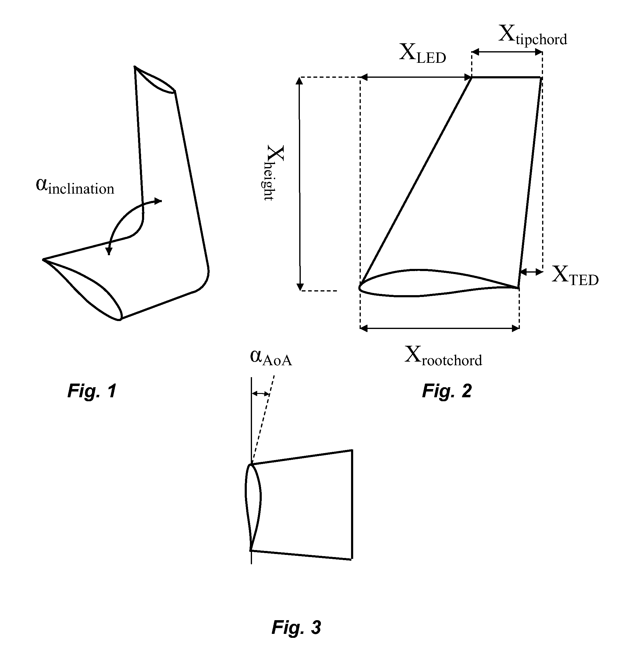
optimal design depends strongly on the height of the winglet, and the invention further relates to a wind turbine comprising a rotor with wind turbine blades each having a root end connected to a hub of the wind turbine and a tip end, the tip end of each of which being equipped with a winglet extending a distance Xheight in a direction perpendicularly to a longitudinal direction of the blade, wherein the combined radius specific
solidity (Solr) of the rotor at the tip end part of the blades substantially is designed in accordance with the formulaSolr=-0.34087·(rR)2+0.6004·(rR)-1.236·(XheightR)2+0.12548·(XheightR)-0.25276+C
[0032]The extension of the winglet may with the present invention exceed the commonly applied 1.2% to 1.5% of the rotor radius with
improved performance of the wind turbine. Thus, the winglet extends preferably in the range of 0.5% to 5% of the radius R of the rotor, and most preferred in the range of 2% to 4% of the radius.
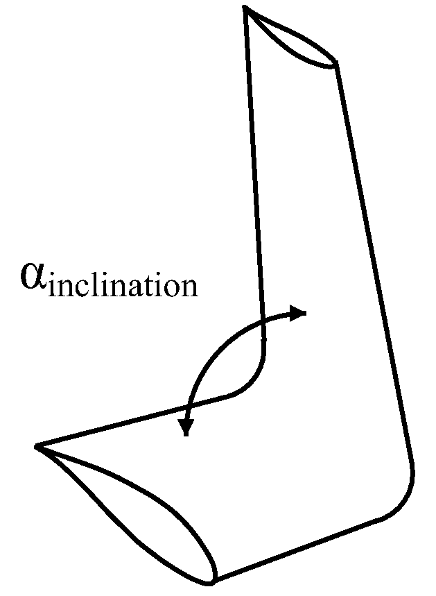
[0035]The winglet may extend to the pressure side, which is the most common in order to avoid interference with the wind turbine
tower, or the winglet may extend to the pressure side as well as to the suction side of the blade. However, it is preferred that the winglets extend said distance (Xheight) to the suction side of the blades of the rotor as it in combination with the present invention has shown to provide an improved performance of the wind turbine.

