Battery Module, Electric Storage Device and Electric System

a battery module and electric storage technology, applied in the direction of cell components, electrical equipment, cell temperature control, etc., can solve the problem of not being able to meet the requirements of a battery module of limited size, and achieve the effect of not being able to meet the requirements of a limited size electric storage devi

Active Publication Date: 2009-10-15
HITACHI VEHICLE ENERGY
View PDF9 Cites 52 Cited by
  • Summary
  • Abstract
  • Description
  • Claims
  • Application Information

AI Technical Summary

Benefits of technology

[0031]According to a twentieth aspect of the present invention, in the battery module according to the eighteenth aspect, it is preferable that a thickness of the casing in a region facing the inlet passage becomes larger from one end side of the casing toward the other end side; and a thickness of the casing in a region facing the outlet passage becomes smaller from one end side of the casing toward the other end side.
[0032]An electric storage device according to a twenty first aspect of the present invention comprises: the battery module according to the first aspect, that comprises the cells electrically connected with one another in series; and a battery control device that controls a state of each of the cells and notifies a higher-rank control device of the state of each the cells.
[0033]An electric system according to a twenty second aspect of the present invention comprises: an electric machine

Problems solved by technology

However, although the related arts are effective for the electric storage device constituted with a battery module size of which is not restricted, they are not necessarily e

Method used


Image

  • Battery Module, Electric Storage Device and Electric System
  • Battery Module, Electric Storage Device and Electric System
  • Battery Module, Electric Storage Device and Electric System

Examples


first embodiment

[0053]A first embodiment of the present invention will now be explained with reference to FIGS. 1 through 8. Firstly, the configuration of an in-vehicle electric system (an electric machine drive system) will be explained with reference to FIG. 6.

[0054]In an operating mode where rotative power is necessary, such as during the power running of the vehicle or at the internal-combustion engine starting, the in-vehicle electric system of the present embodiment drives a motor generator 200, which is a three-phase AC (alternate-current) synchronous motor, as a motor, and supplies driven bodies such as wheels and the engine with the generated rotative power. For this purpose, the in-vehicle electric system of the present embodiment outputs DC (direct-current) power from an electric storage device 100, which is an in-vehicle power source, converts the DC power to three-phase AC power by an inverter device 300, which is an electric power conversion device, and supplies the motor generator 20...

second embodiment

[0186]The second embodiment of the present invention will now be explained with reference to FIG. 9. While in the first embodiment the lithium-ion cells 11 are cylindrical (columnar), in the present embodiment the lithium-ion cells 11 are rectangular (square prism). The length of a side at a cross-section perpendicular to the transverse direction of the lithium-ion cell 11 is the same as the diameter D of the cylindrical lithium-ion cell of the first embodiment.

[0187]The rest of the configuration is identical to that of the first embodiment. Therefore, a component in common with the first embodiment is attached with a reference symbol identical to that of the first embodiment in FIG. 9 and the explanation thereon is omitted.

[0188]According to the present embodiment described above, the operational effects same as those of the first embodiment can be achieved.

third embodiment

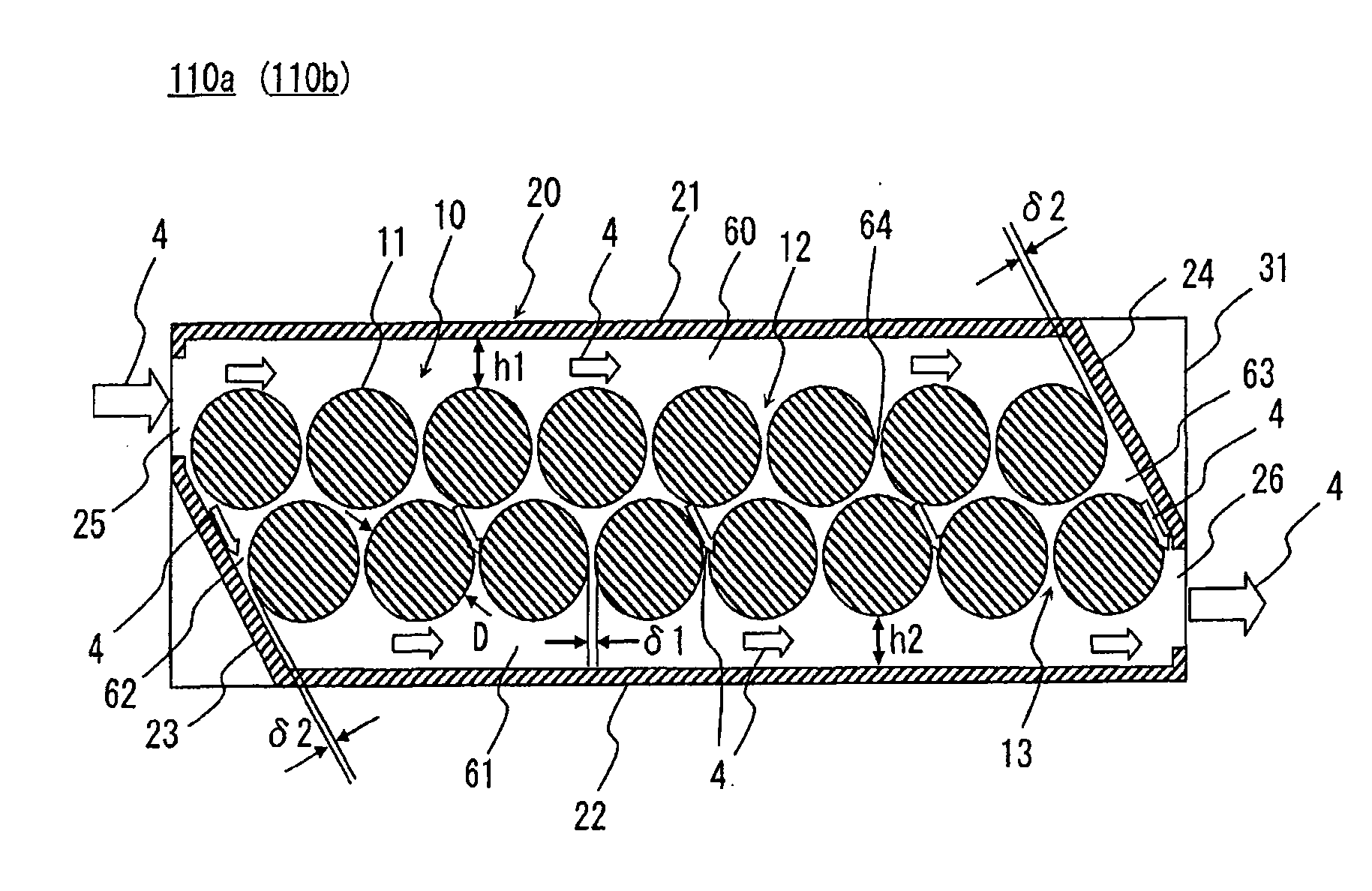
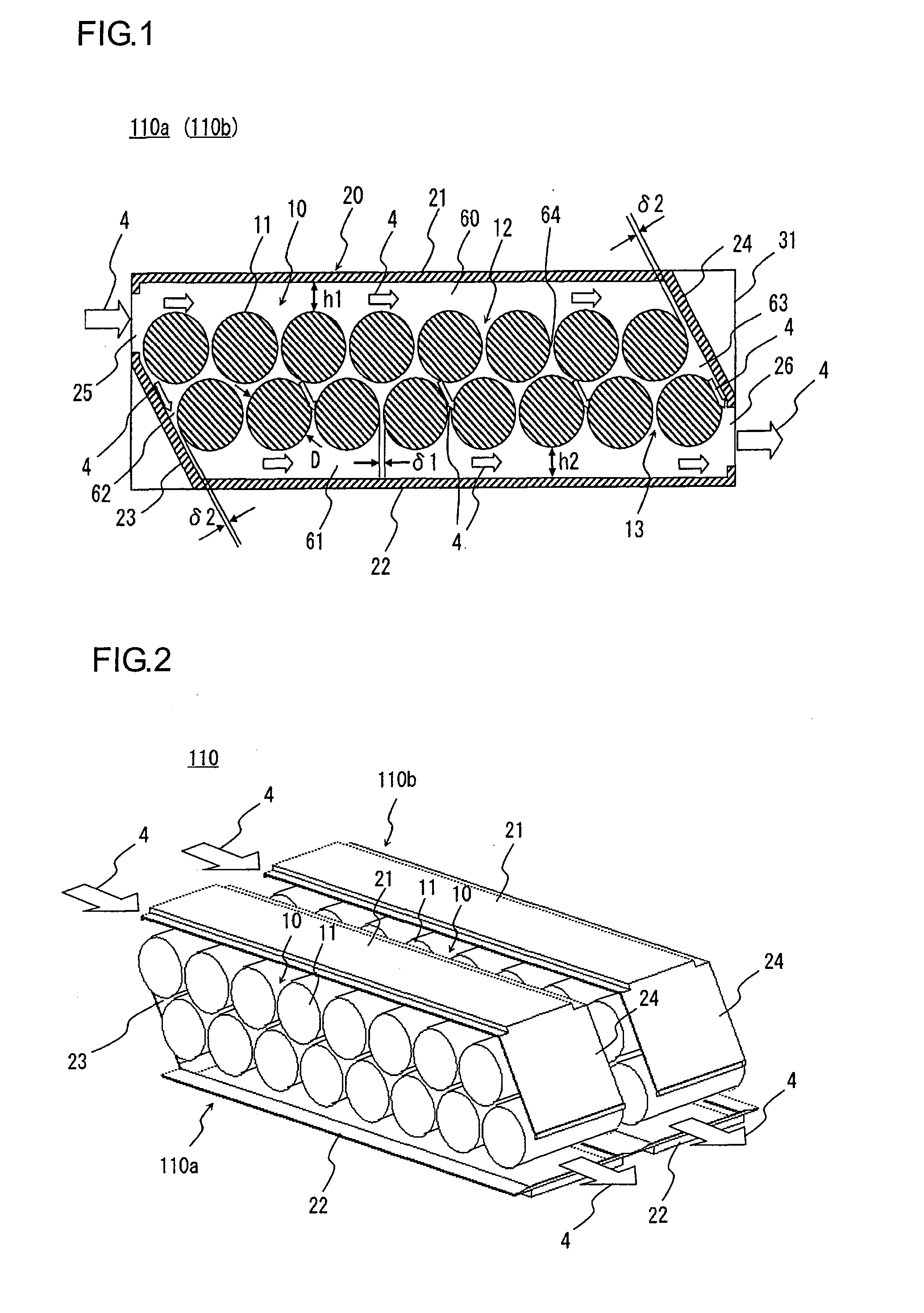
[0189]The third embodiment of the present invention will now be explained with reference to FIG. 10. The present embodiment is a modification of the first embodiment, wherein the height of the inlet-side passage 60. As shown in FIG. 10, the height h1 between the closest regions to the inlet passage forming plate 21 of the lithium-ion cells 11 constituting the first cell string 12 and the inner wall of the inlet passage forming plate 21 in the height direction is configured to be larger than the height of the outlet-side passage 61, i.e., the height h2 between the closest regions to the outlet passage forming plate 22 of the lithium-ion cells 11 constituting the second cell string 13 and the inner wall of the outlet passage forming plate 22 in the height direction. Thus, the size ratio of the height h2 of the outlet-side passage 61 to the diameter D of the lithium-ion cell 11 is configured to be larger than 0.25˜0.5 which is the size ratio of the height h1 of the inlet-side passage 6...


PUM


Abstract

A battery module is configured so that the first cell string and the second cell string are arranged between the first plate member and the second plate member and the second cell string is arranged closer to the second plate member side than the first cell string is and is arranged closer to the outlet side than the first cell string is. At the inlet side of the housing, the inlet is arranged closer to the first plate member than to the second cell string, at least a part between the inlet side of the second cell string and the second plate member is covered by the inlet-side guide plate, and the cooling air is introduced into the housing through the inlet so as to form a flow of the cooling air along the first plate member and a flow of the cooling air along the inlet-side guide plate.

Description

CROSS-REFERENCE TO RELATED APPLICATION[0001]The present application relates to subject matters described in a co-pending patent application Ser. No. 12 / 351,012 filed on Jan. 9, 2009 entitled “CELL MODULE”.INCORPORATION BY REFERENCE[0002]The disclosure of the following priority application is herein incorporated by reference:[0003]Japanese Patent Application No. 2008-097500 filed Apr. 3, 2008BACKGROUND OF THE INVENTION[0004]1. Field of the Invention[0005]The present invention relates to a technology for a battery module including a plurality of cells, an electric storage device and an electric system.[0006]2. Description of Related Art[0007]Japanese Laid Open Patent Publication No. H10-3950 (patent literature 1) and Japanese Laid Open Patent Publication No. 2005-183343 (patent literature 2) disclose a technology for cooling cells.[0008]Patent literature 1 discloses that a plurality of storage battery strings in which a plurality of cylindrical cells aligned with one another in the sa...

Claims


Application Information

Patent Timeline
IPC IPC(8): H01M2/12H01M10/48H01M10/613H01M2/10H01M10/60H01M10/617H01M10/625H01M10/643H01M10/651H01M10/6563H01M10/6566H01M10/658
CPCH01M10/5004H01M10/5016H01M10/5073H01M10/5067H01M10/503H01M10/613H01M10/625H01M10/643H01M10/6563H01M10/6566Y02E60/10
Inventor HARADA, SUSUMUONISHI, MASUHIROSATO, SEIICHITSURUMI, YOSHIHISA
Owner HITACHI VEHICLE ENERGY
Why Eureka
Try Eureka