Air cycle refrigerating/cooling system and turbine unit used therefor

a technology of refrigerating/cooling system and air cycle, which is applied in the direction of domestic cooling apparatus, piston pumps, lighting applications, etc., can solve the problems of reducing efficiency, imposing thrust load on bearings, and not providing sufficient energy efficiency properties, so as to achieve stable high speed rotation, increase system reliability, and high efficiency in compression and expansion

Inactive Publication Date: 2009-10-22
NTN CORP
View PDF16 Cites 22 Cited by
  • Summary
  • Abstract
  • Description
  • Claims
  • Application Information

AI Technical Summary

Benefits of technology

[0016]An object of this invention is to provide an air cycle refrigerating / cooling system where a stable high speed rotation can be attained while keeping the gap between the rotors and the housing microscopic in the turbine unit so that a high efficiency in compression and expansion can be attained, and the durability and the life of the bearing for supporting the main shaft of the turbine unit can be increased so that an increase in the reliability of the system can be achieved, as well as a turbine unit for air cycle refrigerating / cooling for this system.

Problems solved by technology

The use of air as a coolant is preferable from the point of view of environmental protection and safety, but does not provide sufficient properties in terms of energy efficiency in comparison with the case where chlorofluorocarbons, ammonium gas or the like is used.
Fluctuations of this gap prevent a stable high speed rotation, and thus, cause a reduction in the efficiency.
In addition, air which affects the compressor rotor and the turbine rotor makes the thrust force affect the main shaft, and thus, a thrust load is imposed on the bearing for supporting the main shaft.
Therefore, thrust loads as described above cause the durability of the bearing for supporting the main shaft to decrease and the life to become shorter, and thus, decreases the reliability of the turbine unit for air cycle refrigerating / cooling.
It is difficult to put a turbine unit for air cycle refrigerating / cooling into practice, and thus, put an air cycle refrigerating / cooling system into practice without solving the problem of the durability of the bearing as described above.
The above described technologies disclosed in Patent Document 1 and Non-Patent Document 1, however, do not solve the problem where the durability of the bearing against the thrust load for such a high speed rotation decreases.
Therefore, when there is an unstable factor in the control of the thrust bearing, it is difficult to provide a stable high speed rotation while keeping a microscopic gap between the above described rotors and housing.
In the case of a magnetic bearing, there is also a problem of contact at the time of power failure.

Method used


Image

  • Air cycle refrigerating/cooling system and turbine unit used therefor
  • Air cycle refrigerating/cooling system and turbine unit used therefor
  • Air cycle refrigerating/cooling system and turbine unit used therefor

Examples


first embodiment

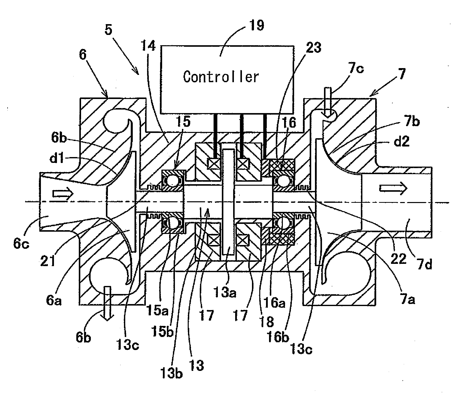
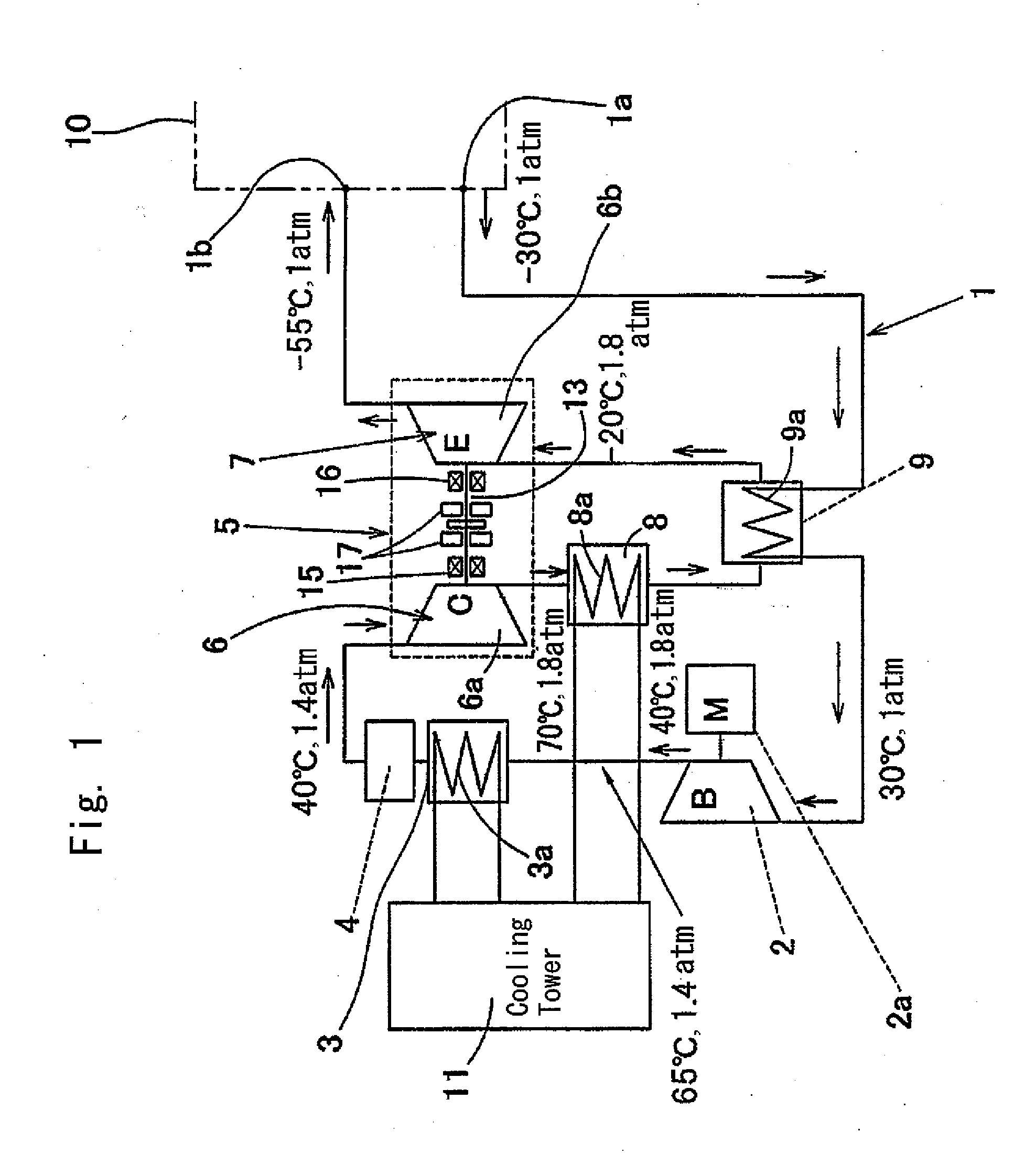
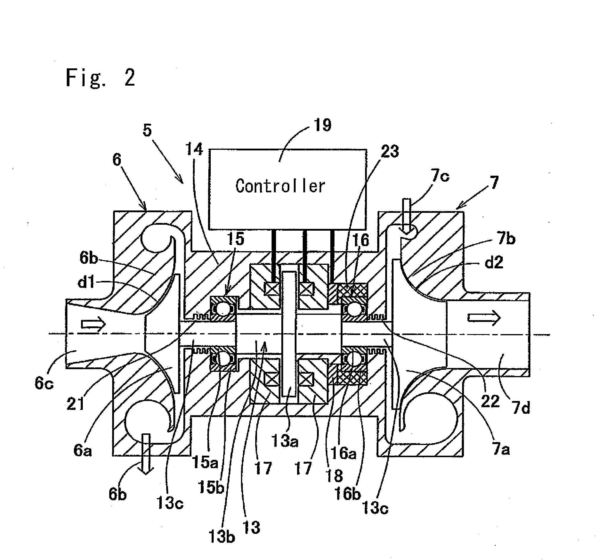
[0051]this invention is described in reference to FIGS. 1 and 2. FIG. 1 shows the entire configuration of the air cycle refrigerating / cooling system. This air cycle refrigerating / cooling system is a system for cooling air in a space to be cooled 10, such as a refrigerator, directly as a coolant and has an air circulation path 1 that reaches from an air inlet 1a to an outlet 1b, which are respective openings in the space to be cooled 10. This air circulation path 1 is provided with a pre-compressing unit 2, a first heat exchanger 3, a dehumidifier 4, a compressor 6 in a turbine unit 5 for air cycle refrigerating / cooling, a second heat exchanger 8, an intermediate heat exchanger 9 and an expansion turbine 7 in the above described turbine unit 5 in this order. The intermediate heat exchanger 9 exchanges heat between the air in the vicinity of the inlet 1a that has flown into the air circulation path 1 and the air of which the temperature rises through the compression in the rear stage ...

second embodiment

[0075]FIG. 3 shows the turbine unit 5 according to this invention. In this turbine unit 5, the main shaft 13 is hollow so that the output side of the expansion turbine 7 and the input side of the compressor 6 are connected to each other via an air vent 83, which becomes a bearing cooling air guiding path within this main shaft 13.

[0076]In the case where the air vent 83 is provided within the main shaft 13, the main shaft 13 is cooled by the air which passes through the air vent 83 so that the bearings 15 and 16, of which the temperature becomes high as a result of high speed rotation, are cooled by heat conductance through the main shaft 13. As a result, the durability of the bearings 15 and 16 is increased.

third embodiment

[0077]Branching paths 83a and 83b having openings on the outer peripheral surface of the main shaft 13 in close proximity to the respective bearings 15 and 16 may be provided to the air vent 83 which passes through the main shaft 13 as in the third embodiment shown in FIG. 4. In the case where these branching paths 83a and 83b are provided, the bearings 15 and 16 are directly cooled by the air that flows through the branching paths 83a and 83b, and thus, the efficiency in cooling the bearings 15 and 16 is increased.


PUM


Abstract

The air cycle refrigerating / cooling system compresses air that has flown in with a compressor (6) in a turbine unit (5) and adiabatically expands the air with an expansion turbine (7) in a turbine unit (5). In the turbine unit (5), a compressor rotor (6a) of the compressor (6) and a turbine rotor (7a) of the expansion turbine (7) are attached to the same main shaft (13), the main shaft (13) is supported by bearings (15) and (16) so as to be freely rotatable, and part or the entirety of the thrust force applied to this main shaft (13) is supported by an electromagnet (17).

Description

BACKGROUND OF THE INVENTION[0001]The present invention relates to an air cycle refrigerating / cooling system where air is used as a coolant and which is used in refrigerated warehouses, low temperature rooms at zero degrees or lower and for air conditioning, and to a turbine unit for air cycle refrigerating / cooling in such a system.[0002]The use of air as a coolant is preferable from the point of view of environmental protection and safety, but does not provide sufficient properties in terms of energy efficiency in comparison with the case where chlorofluorocarbons, ammonium gas or the like is used. In the case where air is used as a coolant in a facility where it can be directly blown into, such as refrigerated warehouses, however, there is a possibility that the total cost can be lowered to that of the existing system by devising a means for omitting fans within a warehouse or defrosting systems. At present, the use of chlorofluorocarbons as a coolant has already been regulated fro...

Claims


Application Information

Patent Timeline
Patent Type & Authority Applications(United States)
IPC IPC(8): F25D9/00F04D25/04F04D29/051
CPCF16C19/54F16C2362/52F25B9/004F16C39/06F25B9/00F25B9/06F16C32/04
Inventor NAKAZEKI, TSUGITOOZAKI, TAKAYOSHIYAMADA, HIROYUKIUMETSU, YOSHIHIDE
Owner NTN CORP
Why Eureka
Try Eureka