
Organic light emitting element and organic light emitting device

a light emitting element and organic technology, applied in the direction of solid-state devices, electric lighting sources, electric lighting sources, etc., can solve the problems of low emission efficiency short lifetime, slow response time, etc., to increase the emission efficiency and lifetime of organic light emitting elements, the effect of reducing voltag

Active Publication Date: 2009-10-22
SAMSUNG DISPLAY CO LTD
View PDF1 Cites 13 Cited by
  • Summary
  • Abstract
  • Description
  • Claims
  • Application Information

AI Technical Summary

Benefits of technology

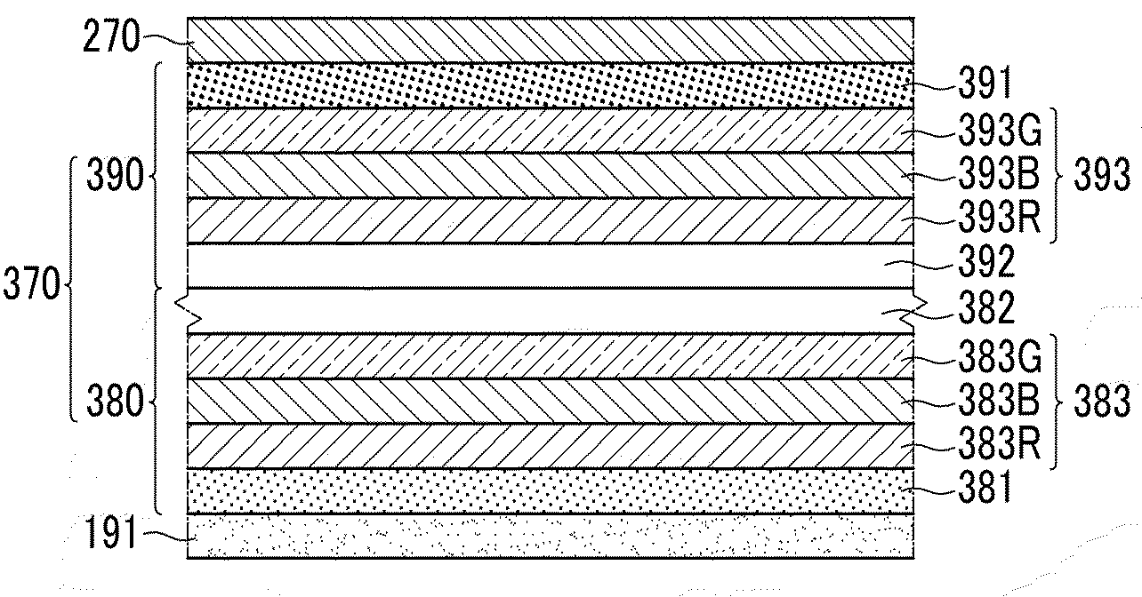
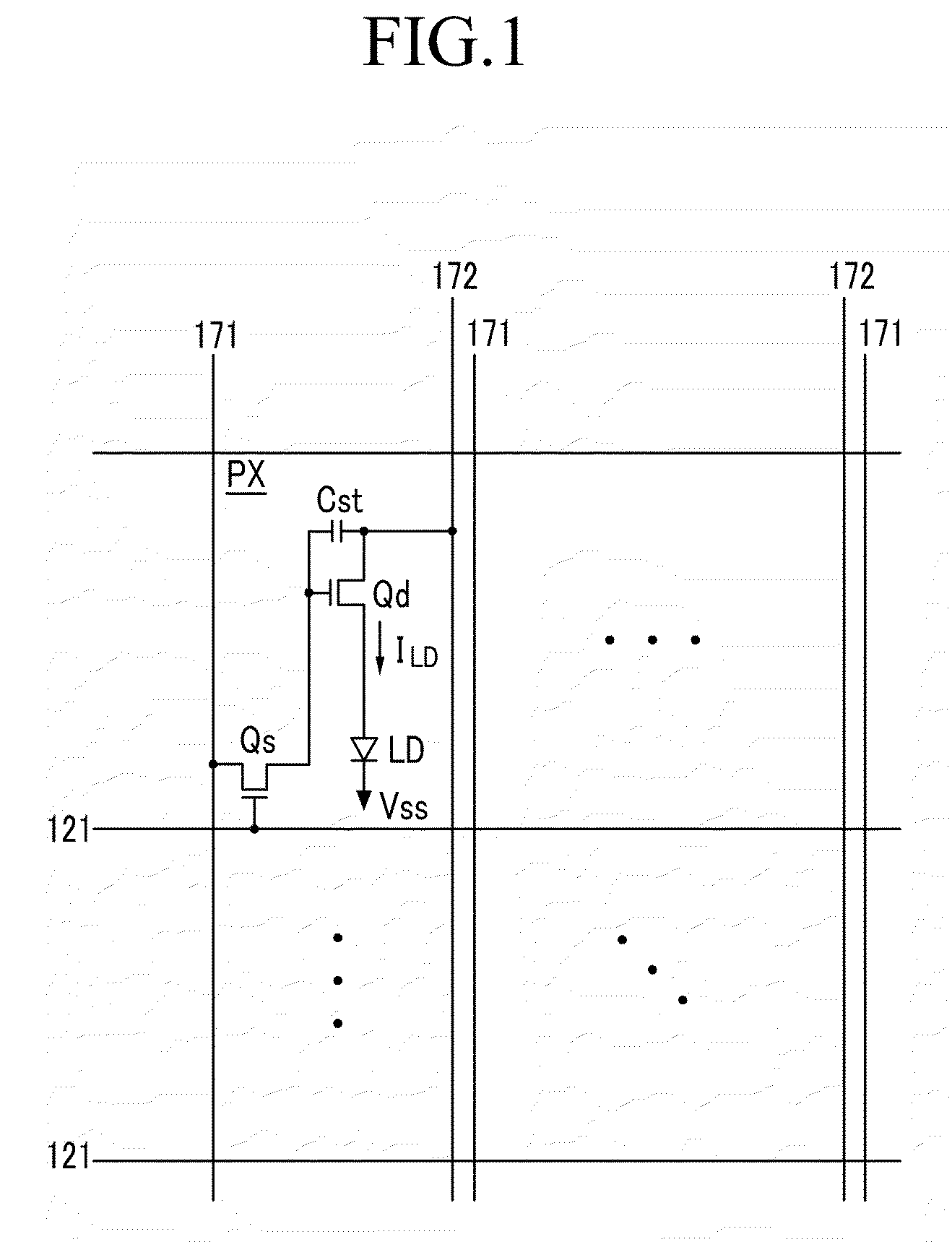
The present invention provides an organic light emitting element and an organic light emitting device with increased emission efficiency and lifetime. The device can be driven at a lower voltage. The invention includes a multi-layered structure with an impurity junction layer, a hole injection layer, and an electron injection layer. The amount of impurity doped in the impurity junction layer is larger than the amount of impurity doped in each of the hole injection layer and the electron injection layer. This results in a more efficient and effective organic light emitting device.

Problems solved by technology

The LCD may also have various problems such as a slow response time and a narrow viewing angle.
However, the organic light emitting element may have low emission efficiency and a short lifetime.
Also, a high voltage may be required to generate the current that is used to cause light emission.

Method used


Image

  • Organic light emitting element and organic light emitting device
  • Organic light emitting element and organic light emitting device
  • Organic light emitting element and organic light emitting device

Examples


Embodiment Construction

[0028]The invention is described more fully hereinafter with reference to the accompanying drawings, in which embodiments of the invention are shown. This invention may, however, be embodied in many different forms and should not be construed as limited to the embodiments set forth herein. Rather, these embodiments are provided so that this disclosure is thorough, and will fully convey the scope of the invention to those skilled in the art. In the drawings, the size and relative sizes of layers and regions may be exaggerated for clarity. Like reference numerals in the drawings denote like elements.

[0029]It will be understood that when an element or layer is referred to as being “on” or “connected to” another element or layer, it can be directly on or directly connected to the other element or layer, or intervening elements or layers may be present. In contrast, when an element is referred to as being “directly on” or “directly connected to” another element or layer, there are no int...


PUM


Abstract

The present invention relates to an organic light emitting element and an organic light emitting device including the same. An impurity layer close to an electrode is doped with a small amount, and an impurity layer for a p-n junction is doped with a large amount, such that a high current may flow under a low voltage.

Description

CROSS-REFERENCE TO RELATED APPLICATION[0001]This application claims priority to and the benefit of Korean Patent Application No. 10-2008-0036223, filed on Apr. 18, 2008, which is hereby incorporated by reference for all purposes as if fully set forth herein.BACKGROUND OF THE INVENTION[0002]1. Field of the Invention[0003]The present invention relates to an organic light emitting element and an organic light emitting device including the same, and particularly to an organic light emitting element including organic light emitting members that are overlapped with a plurality of layers and an organic light emitting device including the same.[0004]2. Discussion of the Background[0005]The recent trend toward lightweight and thin personal computers and television sets has increased the demand for lightweight and thin display devices. Because flat panel displays, such as a liquid crystal display (LCD), satisfy this demand, they are being substituted for conventional cathode ray tubes (CRTs)....

Claims


Application Information

Patent Timeline
Patent Type & Authority Applications(United States)
IPC IPC(8): H01L33/00
CPCH01L27/322H01L51/5036H01L51/5278H01L51/5088H01L51/5092H01L51/5052H10K59/38H10K50/125H10K50/155H10K50/165H10K50/171H10K50/17H10K50/19H05B33/18H05B33/14
Inventor HA, JAE-KOOKCHU, CHANG-WOONGLEE, JOO HYEON
Owner SAMSUNG DISPLAY CO LTD
Learn More