
Coated turbine component and method of coating a turbine component

Active Publication Date: 2009-10-22
SIEMENS ENERGY GLOBAL GMBH & CO KG
View PDF11 Cites 9 Cited by
  • Summary
  • Abstract
  • Description
  • Claims
  • Application Information

AI Technical Summary

Benefits of technology

[0008]Accordingly it is an object of the present invention to provide a turbine component with an improved heat and corrosion resistance and to provide a method of coating a turbine component.
[0051]As in the first preferred embodiment it is possible to diffuse the second coating, which can comprise Al, into the component by CVD or ATP.

Problems solved by technology

However, the various types of environmental damage are still observed, often necessitating premature replacement or repair of components after service exposure.

Method used


Image

  • Coated turbine component and method of coating a turbine component
  • Coated turbine component and method of coating a turbine component
  • Coated turbine component and method of coating a turbine component

Examples


Embodiment Construction

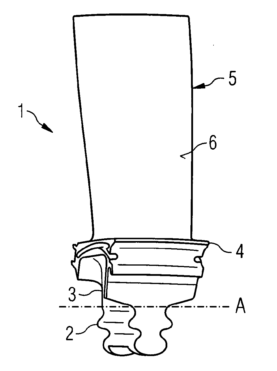
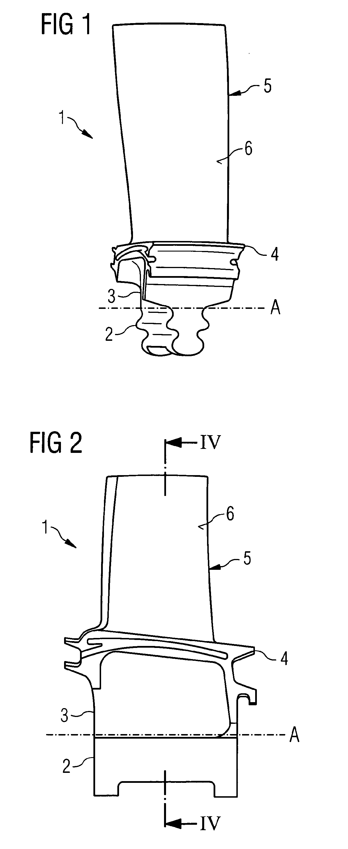
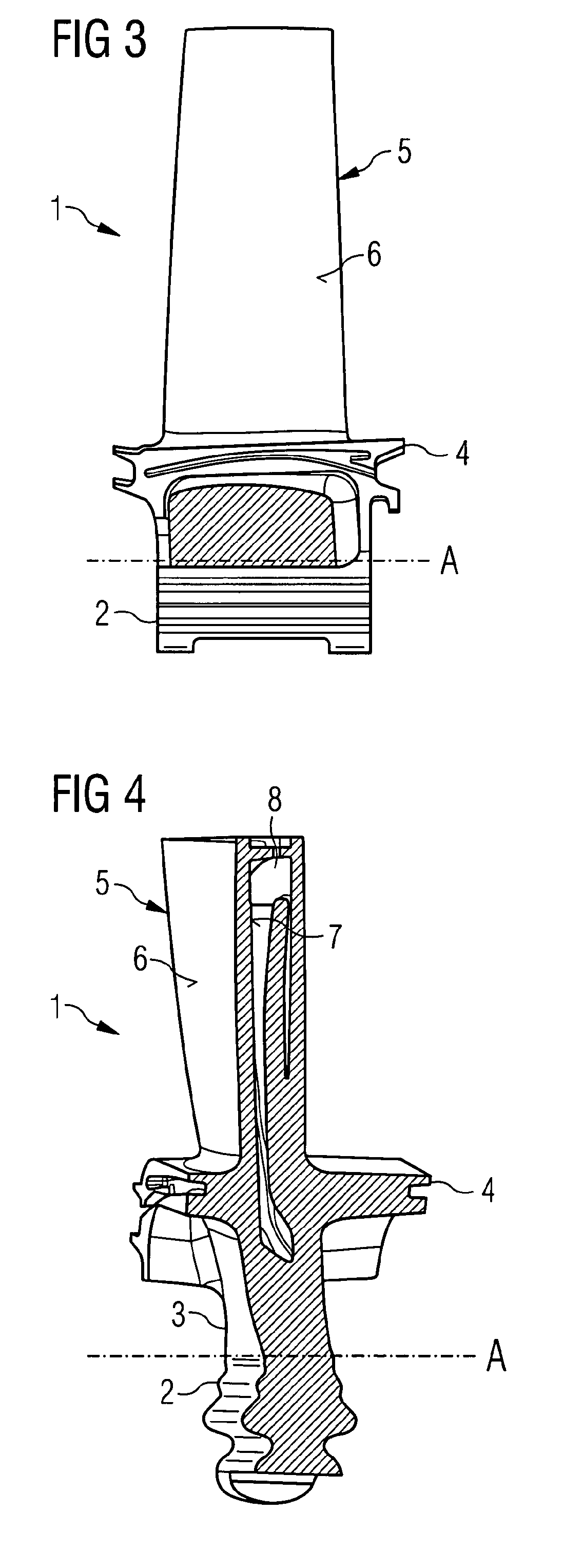
[0074]FIGS. 1 to 5 show a turbine blade 1 having a root 2, a neck 3, a platform 4 and an airfoil 5 with an outer surface 6 and an inner surface 7. In this case the turbine blade 1 consists of the superalloy MarM247 and is provided by directionally solidified casting techniques. The root 2 is connected with the neck 3 which carries the platform 4. The airfoil 5 extends from the platform 4. Inside the airfoil 5 the inner surface 7 defines at least one cooling passage 8 which is depicted in FIG. 4.

[0075]A first diffusion Cr coating is present on all outer and inner surfaces of the blade 1. It is about 5 to 25 μm thick and comprises of 15 to 30 weight-% Cr.

[0076]A second MCrAlY coating is provided on top of the first coating in restricted parts of the blade 1 only, namely on the neck 3, the outer surface 6 of the airfoil 5 and on the whole of the platform 4. The coating has a composition of 30 to 70 weight-% Ni, 30 to 50 weight-% Co, 15 to 25 weight-% Cr, 5 to 15 weight-% Al and up to 1...


PUM

PropertyMeasurementUnit
Molar densityaaaaaaaaaa
Thicknessaaaaaaaaaa
Compositionaaaaaaaaaa

Abstract

Turbine components with different types of coatings on different parts thereof are described. The coatings are chosen such that they are especially adapted to the thermal and corrosive conditions being present on the parts of the component during use. A method to coat a turbine component is also described.

Description

CROSS REFERENCE TO RELATED APPLICATIONS[0001]This application is the US National Stage of International Application No. PCT / EP2006 / 005470 filed Jun. 8, 2006 and claims the benefit thereof.FIELD OF INVENTION[0002]The invention relates to turbine components and to methods of coating a turbine component.BACKGROUND OF INVENTION[0003]Components of gas turbines are operated in a highly aggressive environment which can cause damage to the component in service. The environmental damage may occur in various forms in the hot combustion gas environment, such as particle erosion, different types of corrosion and oxidation, and complex combinations of these damage modes. The rate of environmental damage can be reduced by the use of protective layers.[0004]For example it is known that chromium provides excellent protection against so called type I and type II hot corrosion. In this regard, diffusion coatings produced by the diffusion of chromium and aluminium into the alloy substrate have long be...

Claims


Application Information

Patent Timeline
IPC IPC(8): F01D25/12B05D1/36C23C16/00H05H1/24C23C28/02F01D9/02F01D5/28
CPCF01D5/288F05D2300/611F05D2230/90C23C28/021C23C4/134C23C28/022
Inventor BOX, PAULWHITEHURST, MICK
Owner SIEMENS ENERGY GLOBAL GMBH & CO KG
Learn More