Catalyst and method of manufacture
a catalyst and catalyst technology, applied in the field of catalysts, can solve the problems of reducing conversion efficiency, ammonia slippage, and undesirable presence of ammonia
- Summary
- Abstract
- Description
- Claims
- Application Information
AI Technical Summary
Benefits of technology
Problems solved by technology
Method used
Image

Examples
example 1
[0045]The composition is manufactured by mixing a first catalyst composition portion including ferrierite with a second catalyst composition portion including 2 wt % silver disposed on an alumina porous substrate. The second catalyst composition portion is mixed with the first catalyst composition portion in a weight ratio of 4:1.
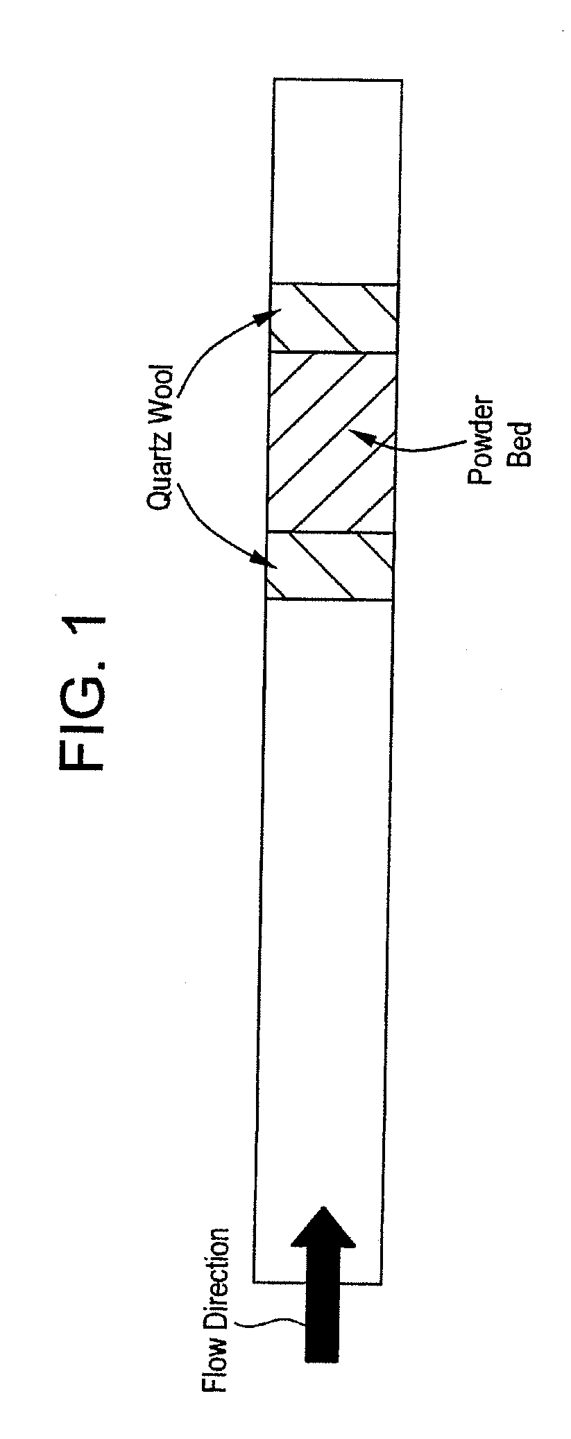
[0046]To determine the NOx reducing capabilities of the composition, it is placed in a furnace between two plugs of quartz wool as shown in FIG. 1.
example 2
[0047]A simulated exhaust stream is discharged into a furnace containing the composition as described in Example 1. The flow of the simulated exhaust stream through the furnace is 3 standard liters per minute. In various tests, the simulated exhaust stream contained nitric oxide in amounts of 475, 610 and 690 parts per million and carbon monoxide in amounts of 250 parts per million. The carbon to nitrogen ratio is set at 6:1. The hydrogen content is 0 parts per million. The water content is set at 7 wt %. The sulfur dioxide and carbon dioxide content is each 0 parts per million. The temperatures in the furnace during the respective experiments are 275, 375 and 430 degrees Celsius. The WSSV (weight specific space velocity) is 674 liters per gram per hour (L / g / hr).
[0048]During the flow of the simulated exhaust stream through the furnace a reductant is introduced into the furnace. The reductant included a 1:1 weight mixture of a C8 blend and a C2-C3 blend. The C8 blend included 64 wt %...
example 3
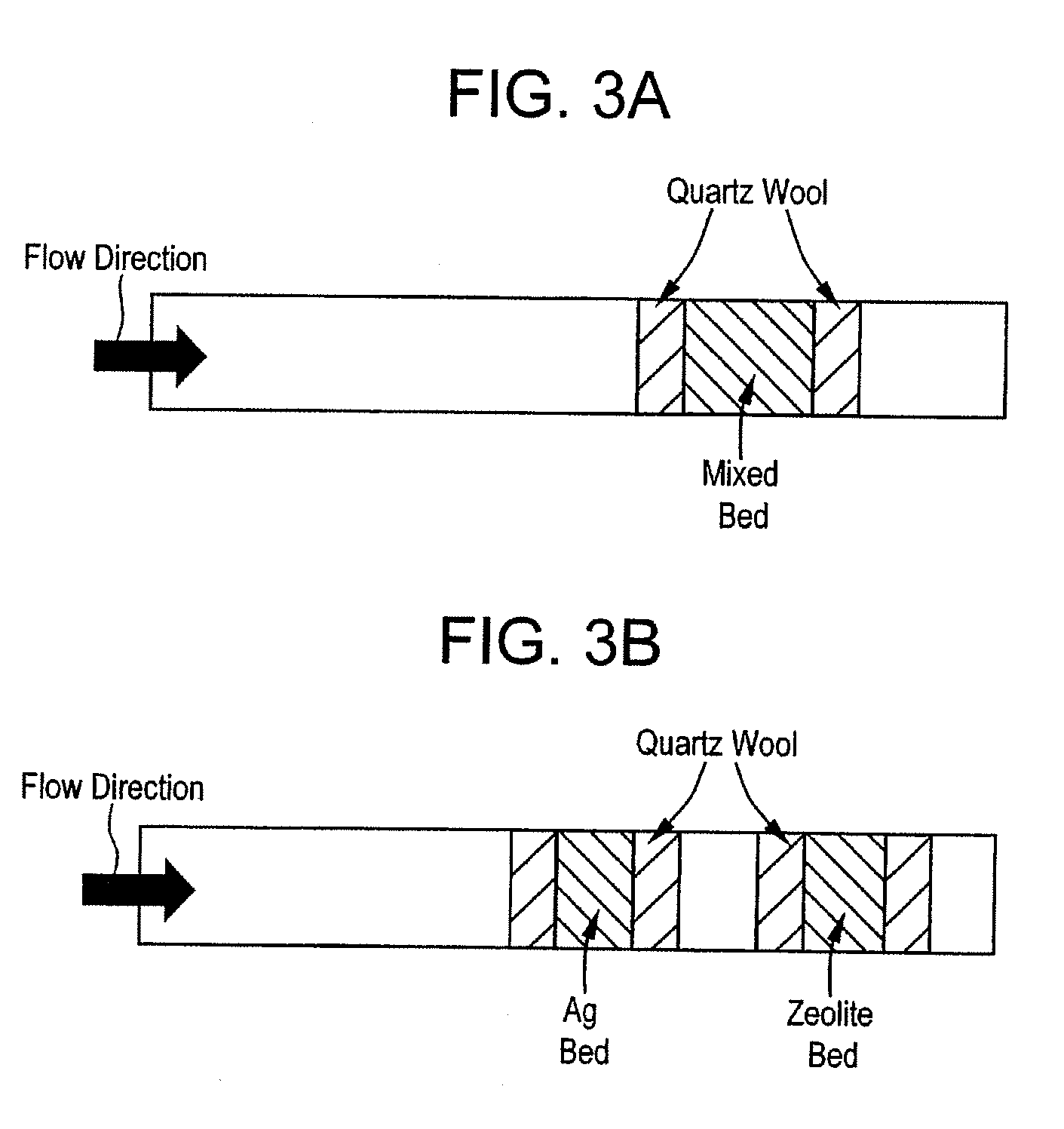
[0052]This example compares the ability to chemically reduce NOx between a first composition (Sample X) in which the first and second catalyst composition portions are intimately mixed together and a second material (Sample Y) in which the first and second catalyst composition portions are not mixed. The configuration of the furnace is shown in FIG. 3(a) and FIG. 3(b), respectively.
[0053]As shown in FIG. 3(a), Sample X is tested by placing a single bed containing the composition between two plugs of quartz wool. FIG. 3(b) shows the first catalyst composition portion and the second catalyst composition portion being placed in a dual bed configuration with each catalyst composition disposed between two plugs of quartz wool. The ferrierite (i.e., first catalyst composition portion) is placed downstream of the silver disposed on the alumina (i.e., the second catalyst composition portion). The remaining test conditions are the same as detailed in the Example 1.
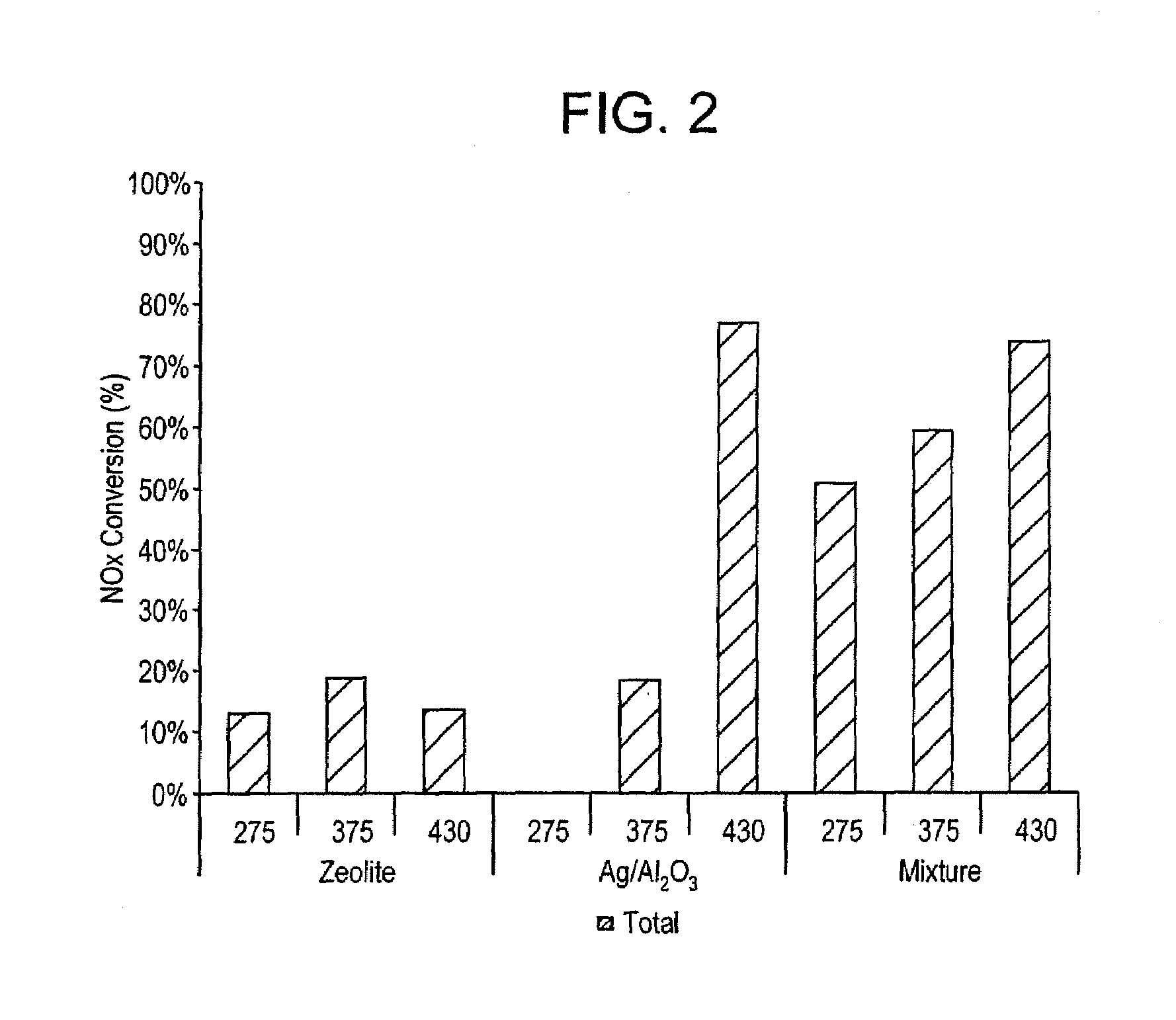
[0054]The results are shown...
PUM
| Property | Measurement | Unit |
|---|---|---|
| Temperature | aaaaa | aaaaa |
| Percent by mass | aaaaa | aaaaa |
| Percent by mass | aaaaa | aaaaa |
Abstract
Description
Claims
Application Information
 - R&D
- Intellectual Property
- Life Sciences
- Materials
- Tech Scout
- Unparalleled Data Quality
- Higher Quality Content
- 60% Fewer Hallucinations
Browse by: Latest US Patents, China's latest patents, Technical Efficacy Thesaurus, Application Domain, Technology Topic, Popular Technical Reports.
© 2025 PatSnap. All rights reserved.Legal|Privacy policy|Modern Slavery Act Transparency Statement|Sitemap|About US| Contact US: help@patsnap.com