Cold trap and cold trap regeneration method

Active Publication Date: 2009-10-29
SUMITOMO HEAVY IND LTD
View PDF2 Cites 19 Cited by
  • Summary
  • Abstract
  • Description
  • Claims
  • Application Information

AI Technical Summary

Benefits of technology

[0008]In this background, a general purpose of the present invention is to provide a cold trap and a method of regenerating a co

Problems solved by technology

However, if the liquefied water or ice drops onto the turbomolecular pump, the turbomolecul

Method used


Image

  • Cold trap and cold trap regeneration method
  • Cold trap and cold trap regeneration method
  • Cold trap and cold trap regeneration method

Examples


Embodiment Construction

[0044]The invention will now be described by reference to the preferred embodiments. This does not intend to limit the scope of the present invention, but to exemplify the invention.

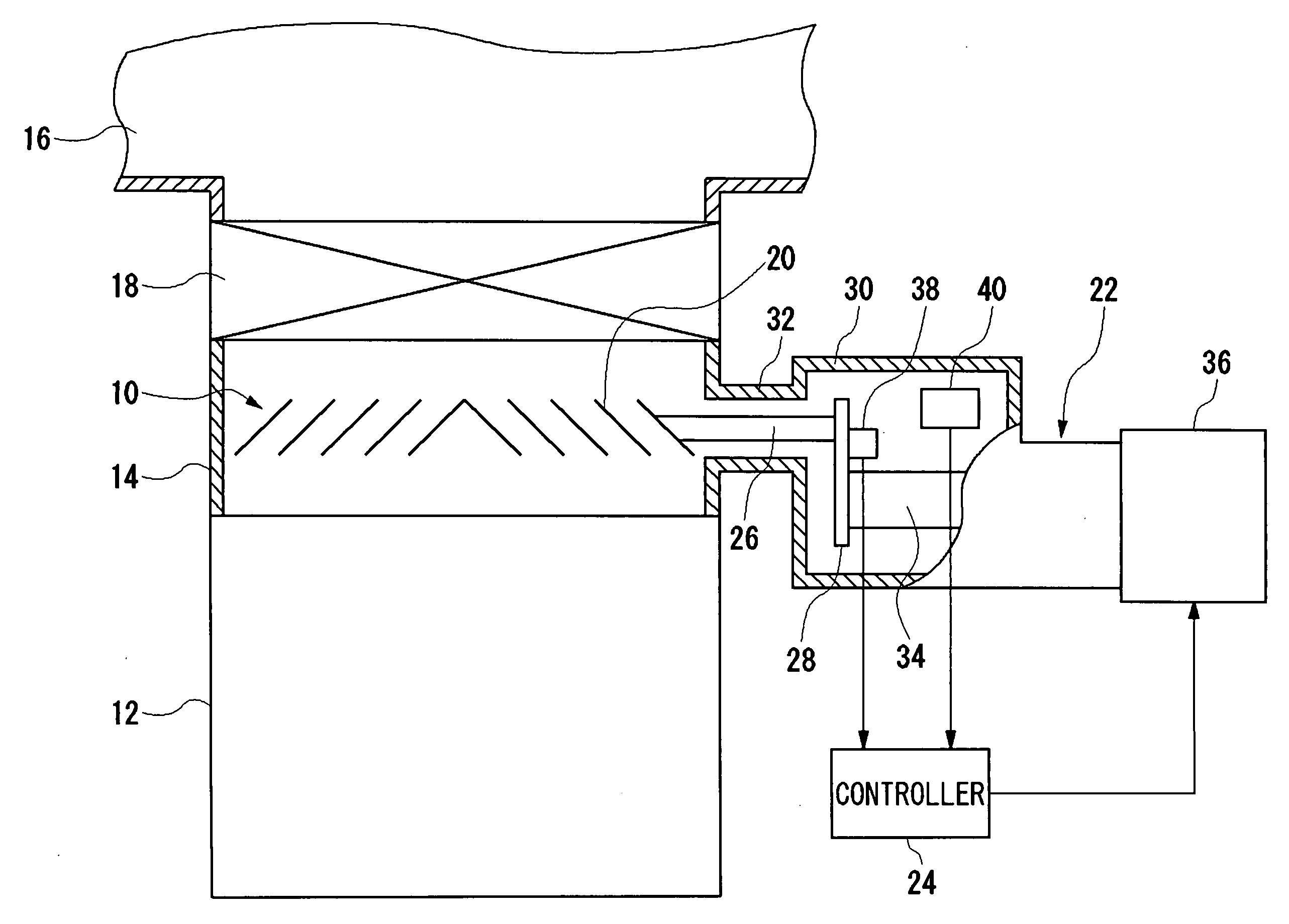
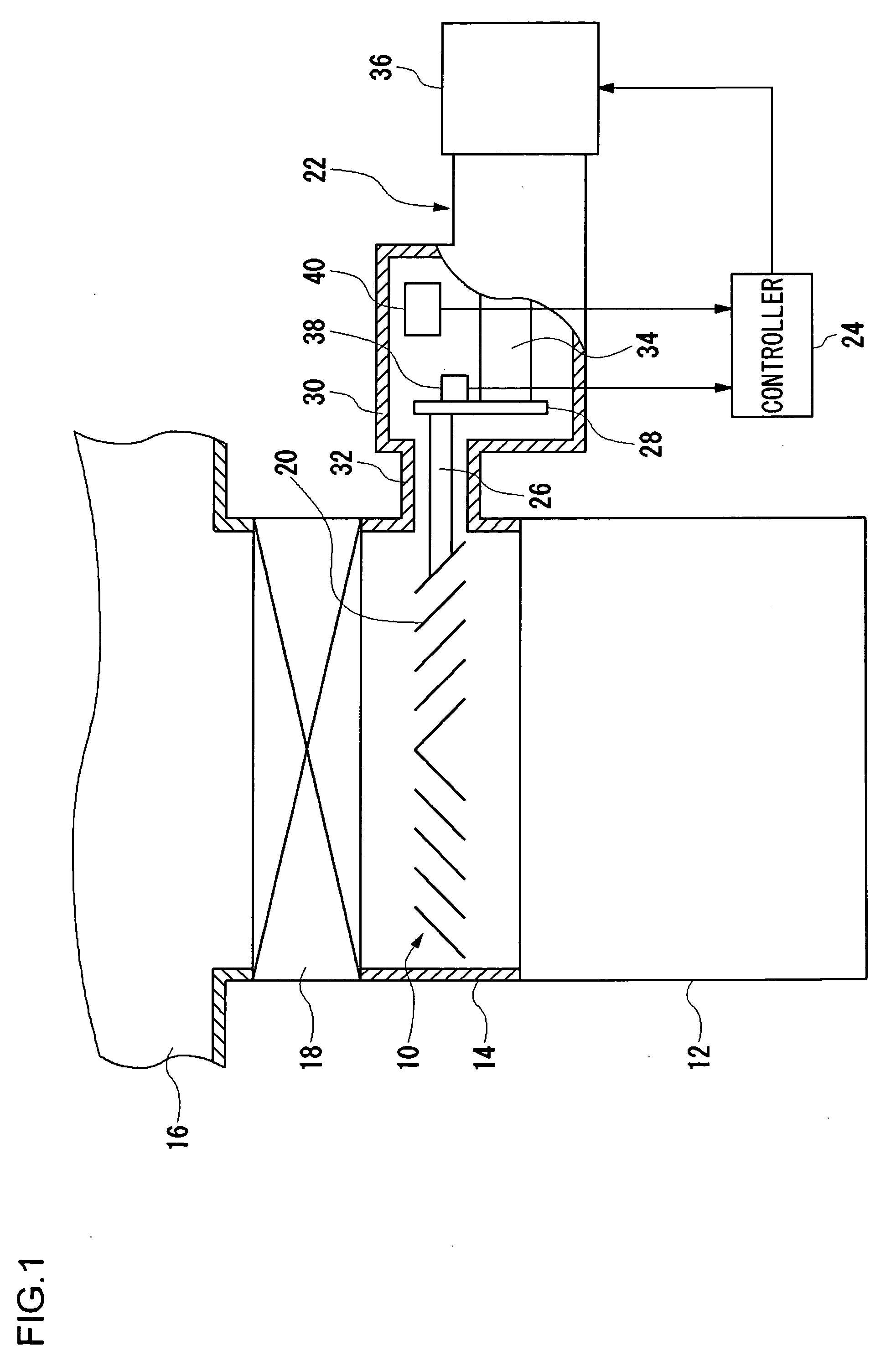
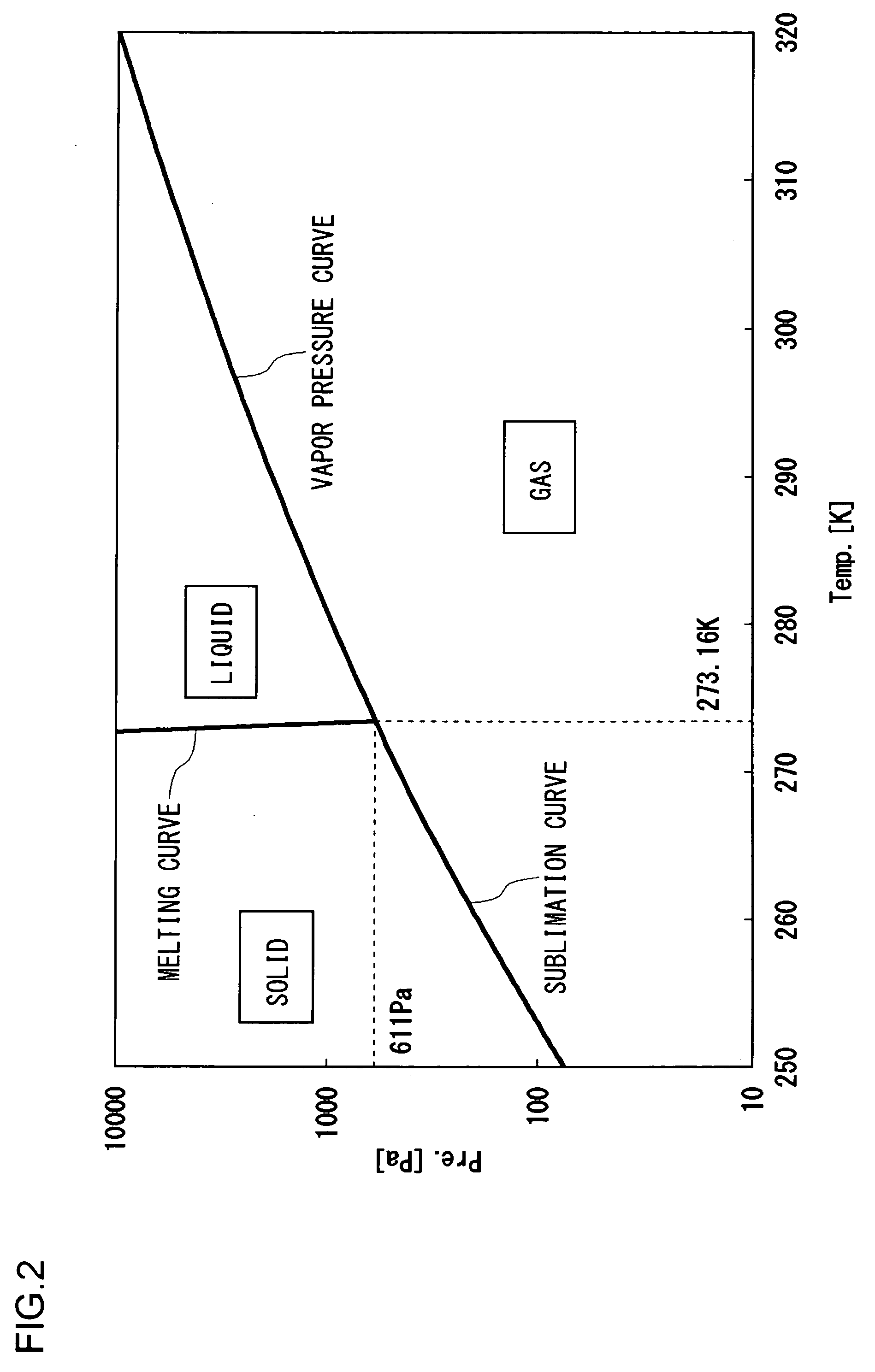
[0045]In one embodiment of the present invention, regeneration time is reduced by performing the regeneration of a cold trap at a high temperature. In a typical regeneration method, regeneration is performed at a low temperature (e.g., below 260 K) in order to evaporate a gas frozen on the surface of a cold trap, bypassing a liquid phase. Liquid phase is avoided in order to prevent vacuum equipment (e.g. a turbomolecular pump) in the neighborhood from being affected. In contrast, according to the embodiment, the ambient pressure around a cold trap being regenerated is adjusted to fall within a pressure range in which a frozen gas is evaporated without being melted. For this reason, regeneration can be performed at a high temperature while avoiding a liquid phase of the captured gas.

[0046]Further, in a ty...


PUM

PropertyMeasurementUnit
Temperatureaaaaaaaaaa
Pressureaaaaaaaaaa

Abstract

A cold trap is provided with a cold panel provided in a pumping path such that the panel is exposed, a refrigerator thermally coupled to the cold panel and operative to cool the cold panel; and a controller configured, in a regeneration process for evaporating a gas frozen on the surface of the cold panel and discharging the gas outside using the vacuum pump, to control the refrigerator so as to raise the temperature of the cold panel to a temperature exceeding a non-liquefaction temperature range and to adjust a pressure in the pumping path at the temperature so that the gas frozen on the surface of the cold panel is evaporated without being melted, the non-liquefaction temperature range being a range in which it is guaranteed that a gas frozen on the surface of the cold trap is evaporated without being melted.

Description

BACKGROUND OF THE INVENTION[0001]1. Field of the Invention[0002]The present invention relates to a cold trap and a method of regenerating a cold trap.[0003]2. Description of the Related Art[0004]A cold trap is an apparatus for removing a gas from the environment by freezing and capturing the gas on its surface. Normally, a cooling apparatus such as a system for supplying a cooling fluid or a cryogenic refrigerator is provided in association with the cold trap so that the surface of the cold trap is cooled to a cryogenic temperature.[0005]For example, patent document No. 1 describes using a cold trap in combination with a dry pump such as a turbomolecular pump. A cold trap is provided in the interior of a vacuum chamber pumped primarily by the dry pump. Gases with a smaller molecular weight such as water vapor are frozen and collected on the cold trap. Other gases with a relatively large molecular weight are pumped by the turbomolecular pump. According to the document, a high degree ...

Claims


Application Information

Patent Timeline
IPC IPC(8): B01D8/00
CPCB01D8/00Y10S417/901F04B37/08B01J3/02F04B37/20
Inventor OIKAWA, KEN
Owner SUMITOMO HEAVY IND LTD
Why Eureka
Try Eureka