Method and Device for Adapting the Efficiency of a Cooler in the Return Circuit of Exhaust Gas in an Internal Combustion Engine

a technology of internal combustion engine and cooler, which is applied in the direction of machines/engines, electric control, instruments, etc., can solve the problems of affecting the temperature of the exhaust gas behind the egr cooler and thus the egr rate, the efficiency of an intact cooler may also change within certain limits, and the emission of internal combustion engines. significant fluctuation, the effect of precise calculation of the egr ra

Active Publication Date: 2009-10-29
ROBERT BOSCH GMBH
View PDF14 Cites 6 Cited by
  • Summary
  • Abstract
  • Description
  • Claims
  • Application Information

AI Technical Summary

Benefits of technology

[0016]Furthermore, the efficiency of an intact cooler may also change within certain limits, and it thus affects the temperature of the exhaust gas behind the EGR cooler and thus the EGR rate. The change in the efficiency is caused, for example, by soot deposits in the EGR cooler. Such soot deposits, however, may again dissipate during certain operating phases such that changes of the cooler efficiency result over the life of a vehicle. While, in current air system models, a constant, permanently specified cooler model is always assumed, example embodiments of the present invention provide for the monitoring function to correct or adapt the cooler model by the ca

Problems solved by technology

Due to the changed density of the recirculated exhaust gas, the variation of the cooling performance results in a change of the EGR rate and may thus result in a significant fluctuation of the emission of the internal combustion engine.
Furthermore, the efficiency of an intact cooler may al

Method used


Image

  • Method and Device for Adapting the Efficiency of a Cooler in the Return Circuit of Exhaust Gas in an Internal Combustion Engine
  • Method and Device for Adapting the Efficiency of a Cooler in the Return Circuit of Exhaust Gas in an Internal Combustion Engine
  • Method and Device for Adapting the Efficiency of a Cooler in the Return Circuit of Exhaust Gas in an Internal Combustion Engine

Examples


Embodiment Construction

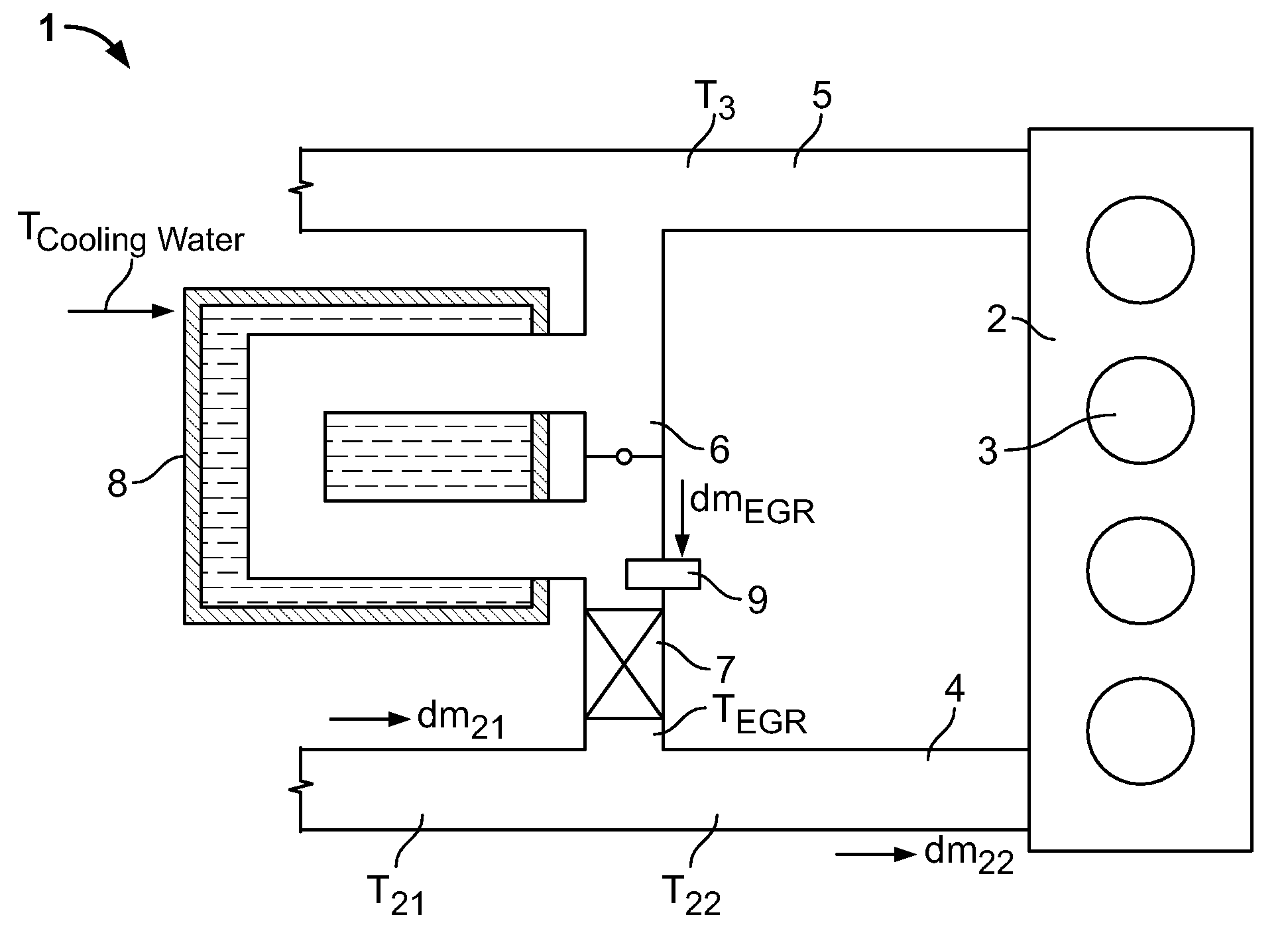
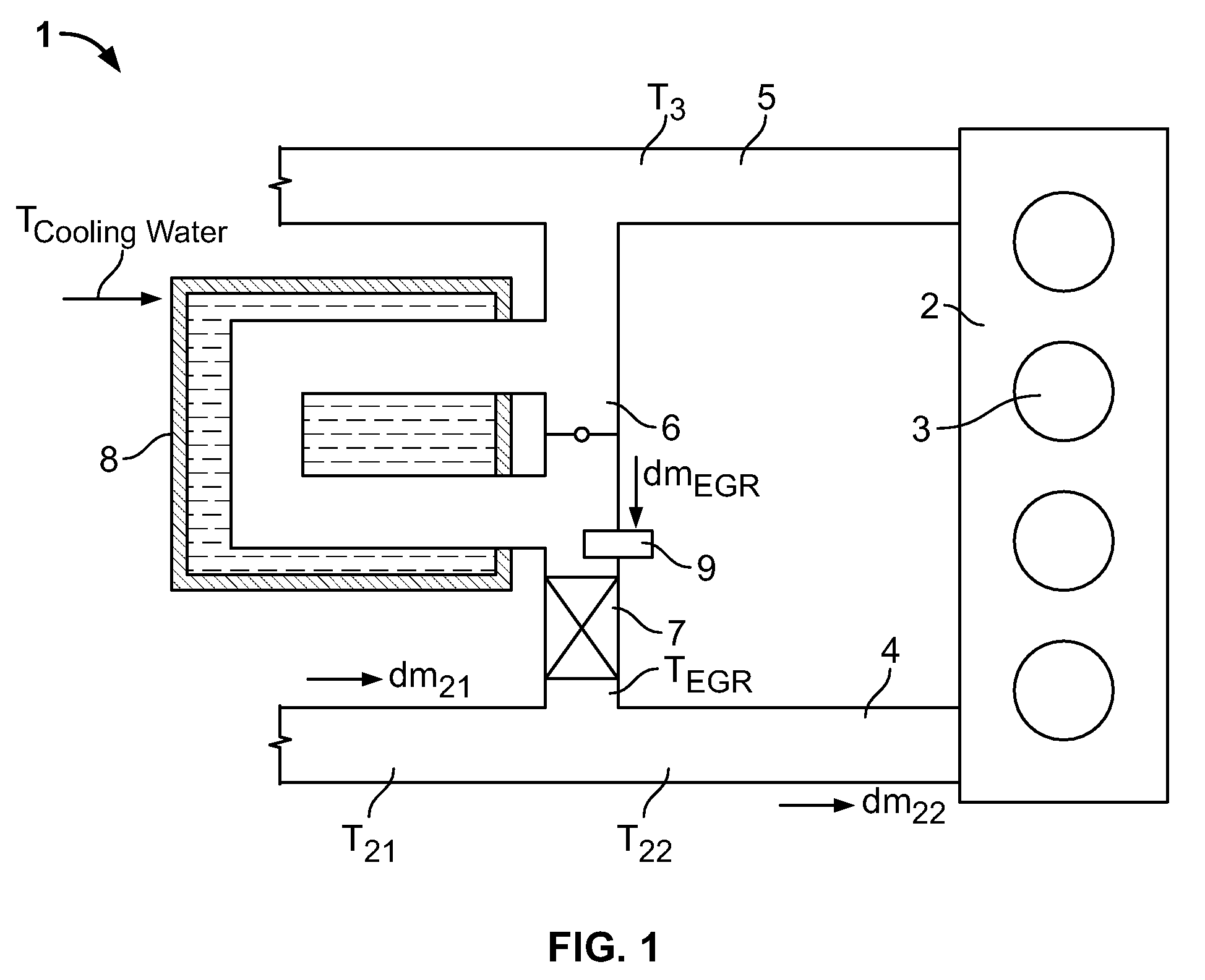
[0030]FIG. 1 shows a schematic representation of an engine system 1 having an internal combustion engine 2 that has four cylinders 3. Via corresponding intake valves (not shown), an air supply 4, e.g. in the form of an intake manifold, supplies air, required for the combustion, to cylinders 3 of internal combustion engine 2. The exhaust gas produced by the combustion in cylinders 3 is removed from internal combustion engine 2 via an exhaust branch 5.

[0031]Between exhaust branch 5 and supply 4, an exhaust gas recirculation line 6 is provided, which has an exhaust gas recirculation valve 7 (EGR valve) in order to feed a portion of the exhaust gas removed through exhaust branch 5 into supply 4. EGR valve 7 is variably adjustable in order to implement a desired exhaust gas recirculation rate (EGR rate) in engine system 1. The EGR rate is defined as the ratio between the exhaust gas mass flow mEGR through recirculation line 6 and the total mass flow m22 of the gas quantity flowing into c...


PUM


Abstract

A method for providing a specification about an efficiency of a cooler for recirculated exhaust gas in an internal combustion engine includes: measuring a temperature of the recirculated exhaust gas cooled by the cooler; and ascertaining the specification about the efficiency of the cooler as a function of the measured temperature of the cooled recirculated exhaust gas. With the aid of the specification about the efficiency of the cooler it is possible to determine a failure of the cooler or to calculate a temperature of the recirculated exhaust gas in order implement an engine control system of the internal combustion engine on the basis of a reliable temperature specification that is not influenced by lag effects.

Description

CROSS-REFERENCE TO RELATED APPLICATIONS[0001]The present application claims priority to Application No. 10 2008 001 418.4, filed in the Federal Republic of Germany on Apr. 28, 2008, which is expressly incorporated herein in its entirety by reference thereto.FIELD OF THE INVENTION[0002]The present invention relates to engine systems for internal combustion engines having an exhaust gas recirculation system, which have a cooler in the exhaust gas recirculation segment for cooling the recirculated exhaust gas.BACKGROUND INFORMATION[0003]In engine systems for internal combustion engines, exhaust gas is recirculated in order to reduce the nitrogen oxide component of the exhaust gas. Due to the increased soot component in the exhaust gas brought about by the exhaust gas recirculation, the quantity of recirculated exhaust gas (indicated by the exhaust gas recirculation rate: EGR rate) is limited with the aid of a constant exhaust gas recirculation rate as a compromise between the nitrogen ...

Claims


Application Information

Patent Timeline
IPC IPC(8): G01M15/10
CPCF02D41/0072F02D41/1446F02D41/2451F02D2041/0067Y02T10/121F02M25/0728F02M25/0731F02M25/0738F02M25/0754F02D2041/007F02M26/25F02M26/28F02M26/33F02M26/47
Inventor BLUMENDELLER, WILHELMMUELLER, HORST
Owner ROBERT BOSCH GMBH
Why Eureka
Try Eureka