Cascode current mirror circuit, bandgap circuit, reference voltage circuit having the cascode current mirror circuit and the bandgap circuit, and voltage stabilizing/regulating circuit having the reference voltage circuit

a current mirror circuit and cascode technology, applied in the direction of amplifiers with semiconductor devices, instruments, amplifiers, etc., can solve the problems of limiting the application of such a voltage regulator circuit, no internal power supply, and frequent voltage level perturbation by ripple effect, so as to reduce the time required for calibrating the voltage regulator circuit error, the effect of reducing the time required for calibration

Inactive Publication Date: 2009-10-29
NAT TAIWAN UNIV
View PDF3 Cites 19 Cited by
  • Summary
  • Abstract
  • Description
  • Claims
  • Application Information

AI Technical Summary

Benefits of technology

[0037]Based on the above information, it is known that the voltage regulator circuit of the present invention, together with the cascode current mirror circuit, the bandgap circuit, the PNP transistor, and the two series resistors, mitigate the temperature effect and the ripple voltage perturbation, thereby forming a reference voltage circuit. The reference voltage circuit is in turn used to generate a reference current free from the temperature effect as well as the ripple voltage perturbation, thereby allowing the operational amplifier circuit to perform precise voltage error calibration. The time required for calibrating the voltage regulator circuit error is also reduced and the voltage of the signal after regulated by the voltage regulator circuit of the present invention is free from the effect of temperature and the ripple voltage perturbation.

Problems solved by technology

In particular, passive RFID tags have no internal power supply.
However, after the rectifier converts the RF signal to a DC voltage level, the voltage level is often perturbed by ripple effect or fluctuates easily due to the effect of external temperature.
However, the aforementioned circuit structure does not take into account of the effect that the environment temperature has on the voltage regulator circuit; therefore, such a circuit structure does not include components that generate negative temperature coefficient and is unable to mitigate the effect that the external temperature has on the voltage regulator circuit, thereby limiting the applications of such a voltage regulator circuit.
However, the aforesaid circuit structure does not take into account of the effect that ripples of the original RF signals have on the voltage regulator circuit.
In addition, the error amplifier design does not adopt the cascode connection, therefore during operation, the perturbation of the voltage regulator circuit caused by ripple voltages cannot be avoided.

Method used


Image

  • Cascode current mirror circuit, bandgap circuit, reference voltage circuit having the cascode current mirror circuit and the bandgap circuit, and voltage stabilizing/regulating circuit having the reference voltage circuit
  • Cascode current mirror circuit, bandgap circuit, reference voltage circuit having the cascode current mirror circuit and the bandgap circuit, and voltage stabilizing/regulating circuit having the reference voltage circuit
  • Cascode current mirror circuit, bandgap circuit, reference voltage circuit having the cascode current mirror circuit and the bandgap circuit, and voltage stabilizing/regulating circuit having the reference voltage circuit

Examples


Embodiment Construction

[0044]The following illustrative embodiments are provided to illustrate the disclosure of the present invention, these and other advantages and effects can be apparently understood by those in the art after reading the disclosure of this specification. The present invention can also be performed or applied by other different embodiments. The details of the specification may be on the basis of different points and applications, and numerous modifications and variations can be devised without departing from the spirit of the present invention.

[0045]The following embodiments further illustrate the points of the present invention in detail, however the scope of the invention is not limited to any points.

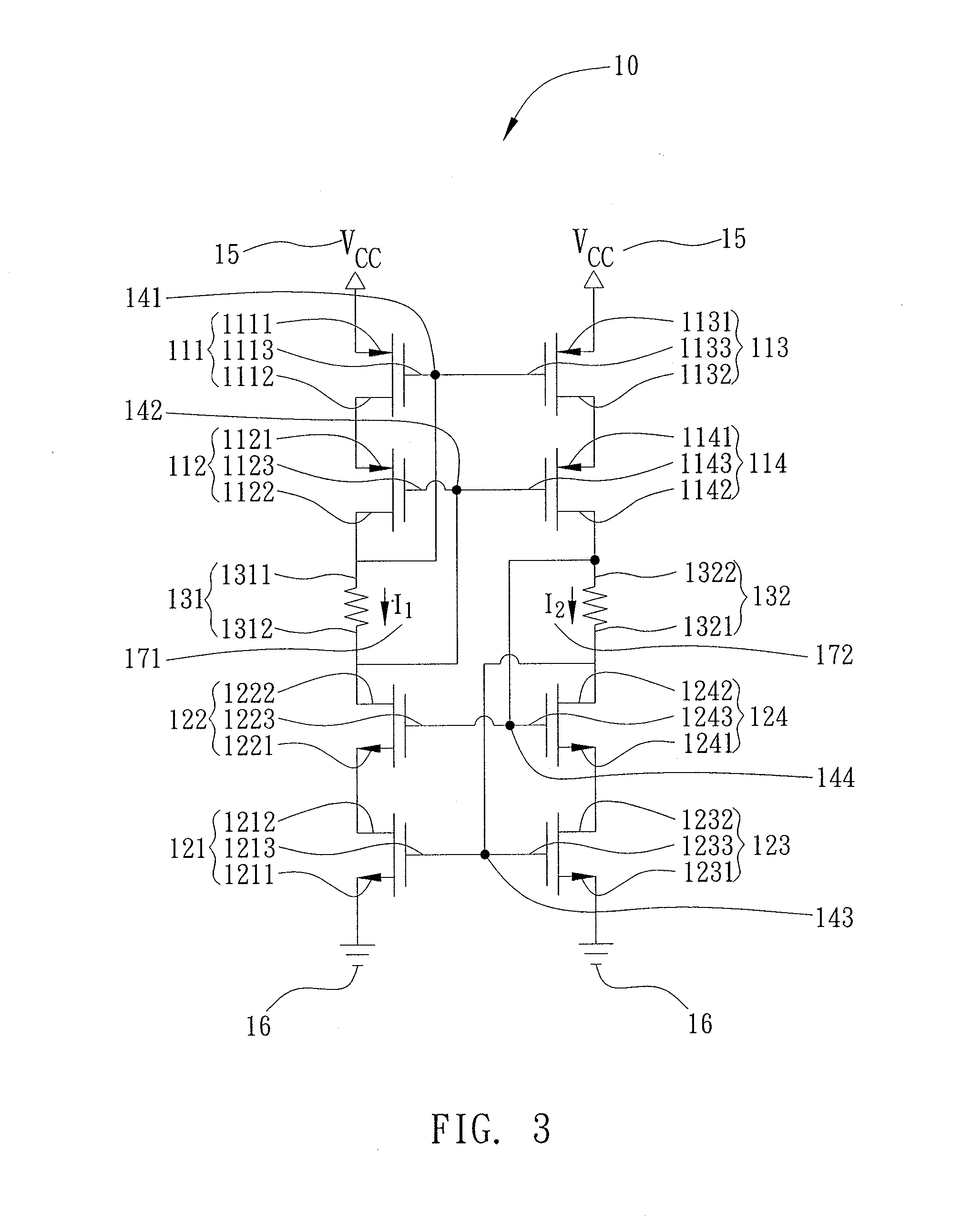
[0046]Referring to FIG. 3, a structure of a cascode current mirror circuit of the present invention is shown. A cascode current mirror circuit 10 of the present invention includes: a first PMOS transistor 111, a second PMOS transistor 112, a third PMOS transistor 113, and a fourth PMOS t...


PUM


Abstract

A cascode current mirror circuit and a bandgap circuit are provided. The circuits are used together and function as a reference voltage circuit. The reference voltage circuit outputs a reference current resistant to temperature variation and ripple-voltage. Accordingly, a voltage stabilizing/regulating circuit corrects error voltage precisely and promptly, and the resultant voltage is temperature insensitive and ripple-voltage-independent.

Description

BACKGROUND OF THE INVENTION[0001]1. Field of the Invention[0002]The present invention relates to voltage regulator circuits, and more specifically, to a voltage regulator circuit for RF signals.[0003]2. Description of Related Art[0004]Radio frequency identification system is an automatic identification method that involves affixing a small electronic tag to a product which may be checked and monitored by a device known as “reader” which in turn transmits the data stored in the electronic tag back to the system via a wireless RF means, thus achieving remote authentication, tracking, control, management and handling.[0005]The electronic tags can be categorized into two general varieties, passive or active. In particular, passive RFID tags have no internal power supply. The minute electrical current induced in the antenna by the incoming radio-frequency (RF) signal provides just enough power for the CMOS integrated circuit in the tag to power up and transmit a response.[0006]Upon recei...

Claims


Application Information

Patent Timeline
Patent Type & Authority Applications(United States)
IPC IPC(8): G05F3/16G05F3/20H03F3/16
CPCG05F3/30H03F1/223H03F3/195H03F3/45085H03F2203/45676H03F2203/45648H03F2203/45651H03F2203/45674H03F2203/45646
Inventor LIU, CHI-ENKIANG, JEAN-FU
Owner NAT TAIWAN UNIV
Why Eureka
Try Eureka