Shielded and insulated heat removing system

a technology of shielding or insulating heat, applied in lighting and heating apparatus, electrical apparatus casings/cabinets/drawers, instruments, etc., can solve the problems of significant interference with output and thereby the quality of output images, and the output of circuit output degradation, so as to improve the heat transfer

Active Publication Date: 2009-10-29
SHENZHEN MINDRAY BIO MEDICAL ELECTRONICS CO LTD
View PDF13 Cites 27 Cited by
  • Summary
  • Abstract
  • Description
  • Claims
  • Application Information

AI Technical Summary

Benefits of technology

[0020]3) In some embodiments, by applying the thermal conductive medium between the base of the heat dissipating device and the electronic circuit or device, the heat generated by the electronic device may be transferred to heat sink base more effectively.
[0021]4) In some embodiments, the use of the heat pipe, the plurality of fins, pins, or other geometrical shapes for the heat sink, the blower / fan, and / or the liquid cooling device, may enhance heat transfer.

Problems solved by technology

These insulators do not serve the purpose of dissipating heat or providing electromagnetic shielding; these heat dissipating devices usually do not provide electrical insulation or electromagnetic shielding; and the electromagnetic shielding cases usually do not serve the purposes of dissipating heat or providing electrical insulation.
Nonetheless, aluminum is electrically conductive, and thus the aluminum studs may sometimes unavoidably or inadvertently connected with the circuit boards electrically and thus create electromagnetic interference.
Such electromagnetic interference results in degradation in the output of the circuits.
For example, in color Doppler ultrasound diagnostic systems, especially, the electromagnetic interference caused by the use of such aluminum studs is likely to cause continuous wave (CW) interference, which may result in significant interference with the output and thereby the quality of the output images.

Method used


Image

  • Shielded and insulated heat removing system
  • Shielded and insulated heat removing system
  • Shielded and insulated heat removing system

Examples


Embodiment Construction

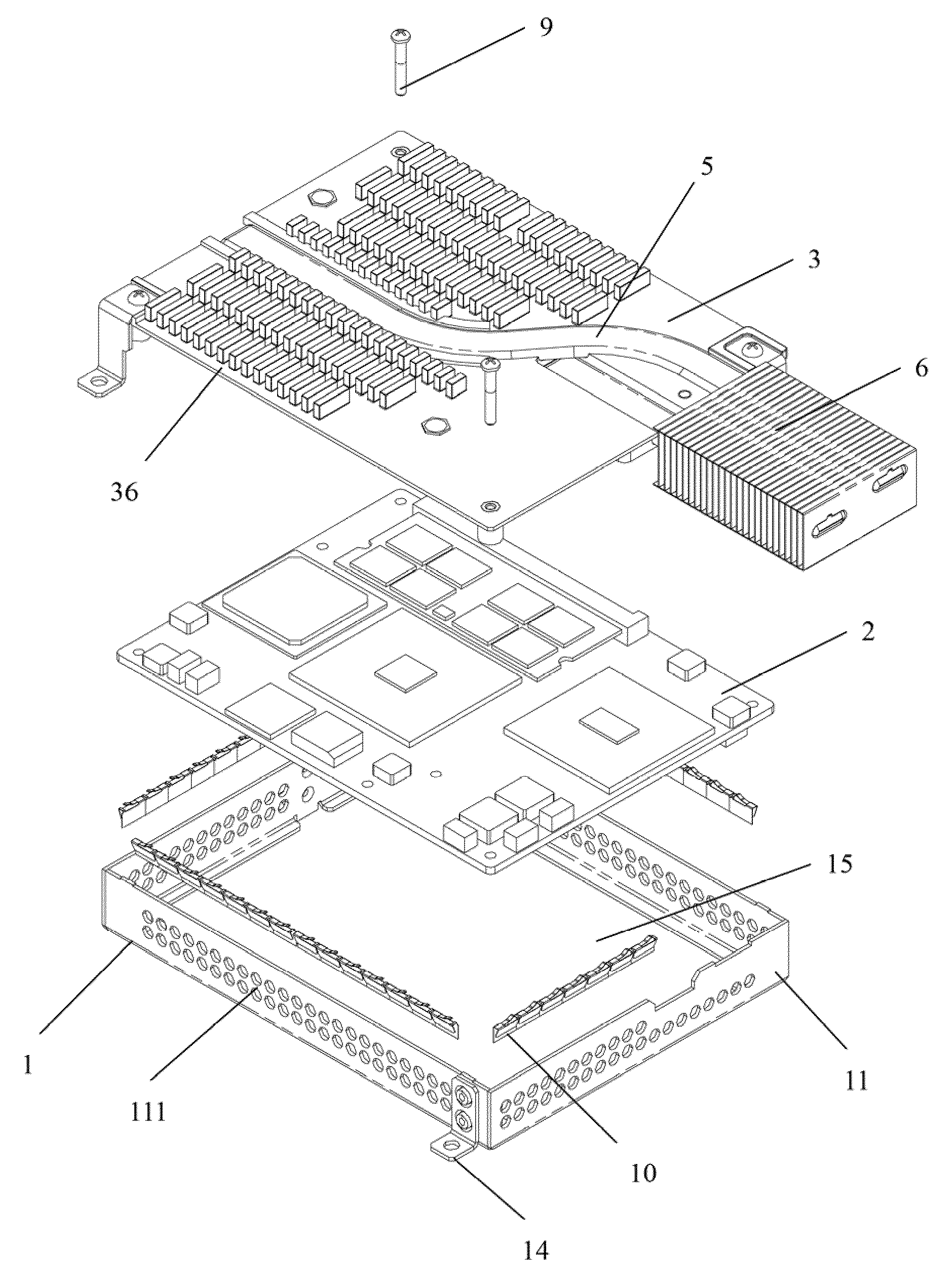
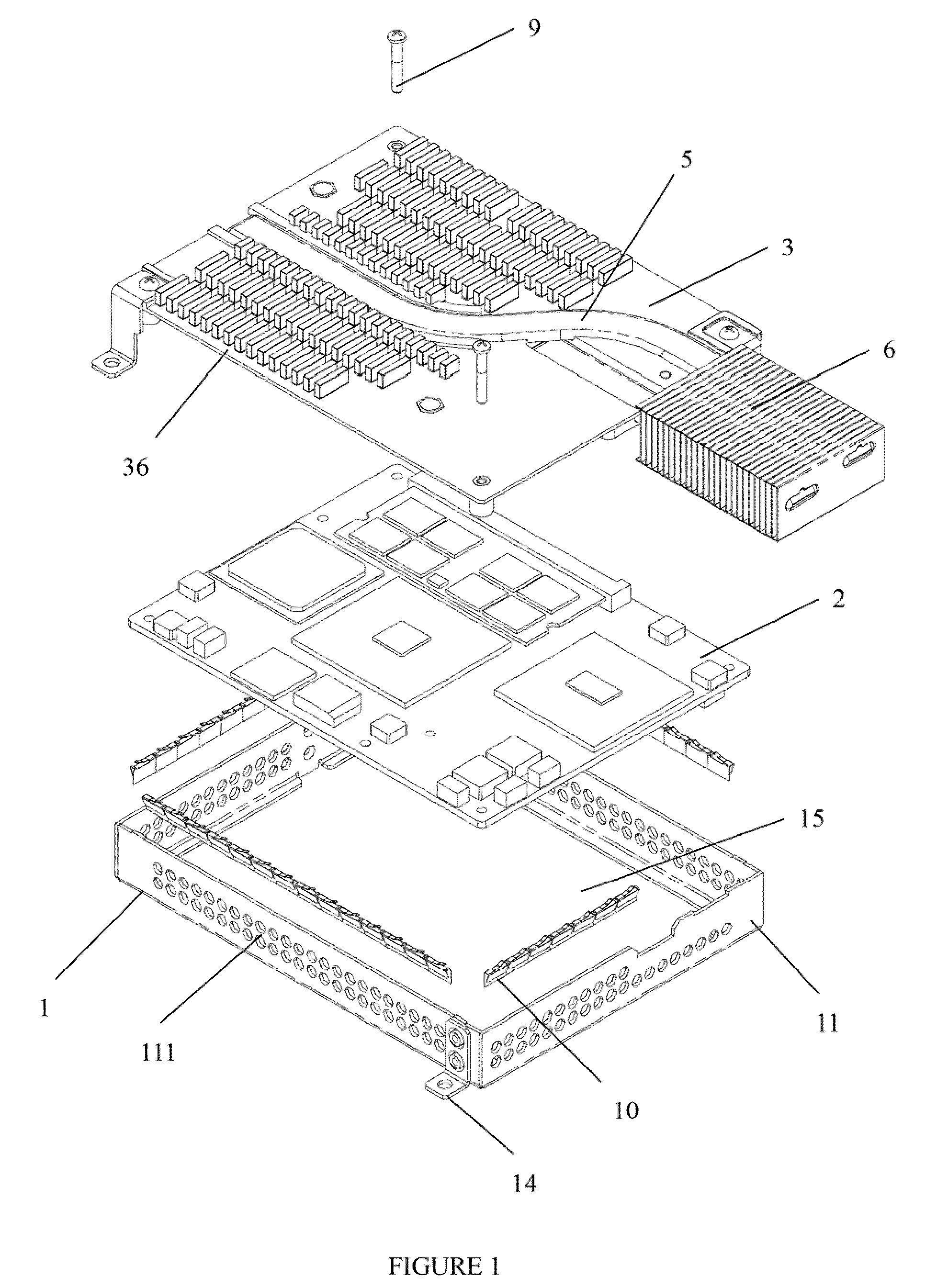
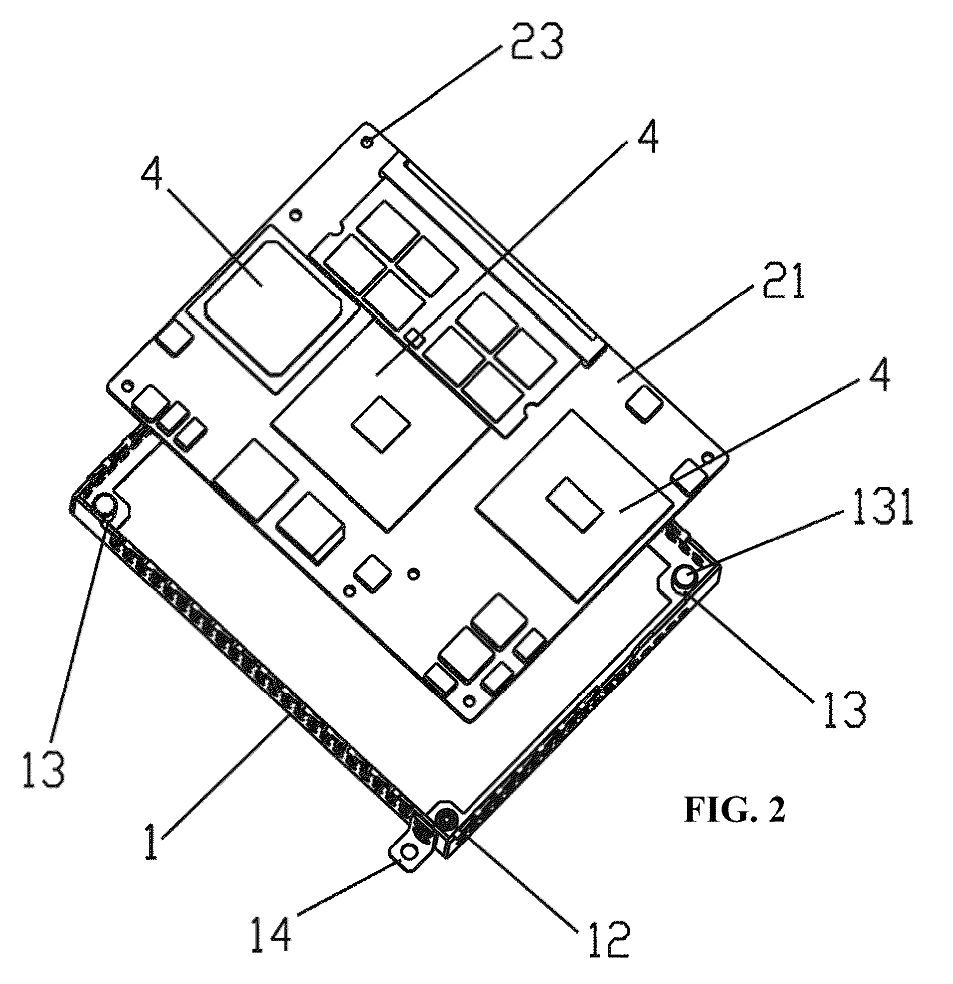
[0030]As shown in FIGS. 1 to 7, an electromagnetically shielded and electrically insulated heat dissipating system according to one embodiment comprises a electromagnetic shielding case 1, a heat sink base 3, and a circuit board 2 which comprises at least one electronic device 4 for which heat dissipation is desired. The base of the heat dissipating device 3 may be fixedly or removably attached to the electromagnetic shielding case 1 and jointly defines an electromagnetically shielded space 15 with the electromagnetic shielding case 1 to provide electromagnetic shielding within the enclosed space in some embodiments. The circuit board 2 is disposed inside the electromagnetic shielded space 15, with the circuit board 2 being electrically insulated from both the electromagnetic shielding case 1 and the base 3 of the heat dissipating device. In some embodiments, the electromagnetic shielding case encompasses or accommodates a part of the electronic device, wherein electromagnetic shiel...


PUM


Abstract

Various embodiments disclose a shielded or isolated heat dissipating system comprising a case, a heat sink base, and a circuit board comprising at least one electronic device for which heat dissipation is desired. The heat sink base is attached to the case and together with the shielding case defines an enclosed space within which electromagnetic interference is reduced. Both heat-dissipation function and electromagnetic shielding function may be achieved by the combination of the heatsink base and the case while maintain electrical isolation with one or more specially treated components. The space required for mounting the system may also be reduced without adversely affecting normal and stable operation of the electronic device.

Description

CROSS-REFERENCE TO RELATED APPLICATION[0001]This application claims the benefit under Title 35, United States Code, §119(a)-(d) or §365(b) from Chinese Patent Application No. 200810066861.4 which was filed on Apr. 25, 2008 into State Intellectual Property Office of the People's Republic of China.FIELD OF THE INVENTION[0002]Various embodiments the invention relate to a shielded or insulated heat removing system.BACKGROUND OF THE INVENTION[0003]In today's electronic devices, heat dissipating structures or devices, e.g., heat sinks in some embodiments, are used for dissipating heat. Some electronic devices employ shielding cases for electromagnetic shielding. Some electronic devices adopt one or more insulating pads or components for electrical insulation. Nonetheless, each of these heat dissipating devices, electrical insulators, and electromagnetic shields usually serves one dedicated purpose. For example, heat sinks for central processing units (CPUs) or computer graphics cards used...

Claims


Application Information

Patent Timeline
Patent Type & Authority Applications(United States)
IPC IPC(8): H05K7/20H05K9/00
CPCG06F1/203
Inventor CHEN, GUOYINGLIU, GUOTAOZHU, DAHUIXIAO, XUNHUA
Owner SHENZHEN MINDRAY BIO MEDICAL ELECTRONICS CO LTD
Why Eureka
Try Eureka