Method of operating a satellite navigation receiver

a satellite navigation and receiver technology, applied in the field of satellite navigation receiver operation, to achieve the effect of high correlation value, significant improvement of performance, and sensitive to errors

Inactive Publication Date: 2009-11-05
DEUTSCHES ZENTRUM FUER LUFT & RAUMFAHRT EV
View PDF9 Cites 21 Cited by
  • Summary
  • Abstract
  • Description
  • Claims
  • Application Information

AI Technical Summary

Benefits of technology

[0029]The final equation (6) can now be used for the simulations of the approach proposed by the present disclosure called RANCO. The thresholds for the comparisons can be set relative to the variation (sigma) of the predicted error distributions for each ranging source individually. This allows the use of all available information and accounts for the influence of effects depending on elevation angles. Setting the threshold also relative to the variances of the currently used subset will improve the performance significantly. With the Inverse of the Covariance Matrix of the ranging sources W and the vector of variances a, the overall variance of the residuals of the comparison is therefore:
[0030]The preselection of subsets is of high importance for the performance of the described technique. This is due to the fact that there exists a huge amount of subsets (n choose k) that would take a long time to process. Further, many of the subsets do have a weak geometry, because the normal vectors between the receiver and the individual satellites are in about the same direction, and are therefore very sensitive to errors. Hence, a selection technique that evaluates the subsets with respect to their geometry is useful. A first approach computes the condition of the geometry matrices and thus evaluates the orthogonality of

Problems solved by technology

As there is used only the minimum necessary number of ranging sources to compute an estimate, a signal bias translates directly i

Method used


Image

  • Method of operating a satellite navigation receiver
  • Method of operating a satellite navigation receiver
  • Method of operating a satellite navigation receiver

Examples


Embodiment Construction

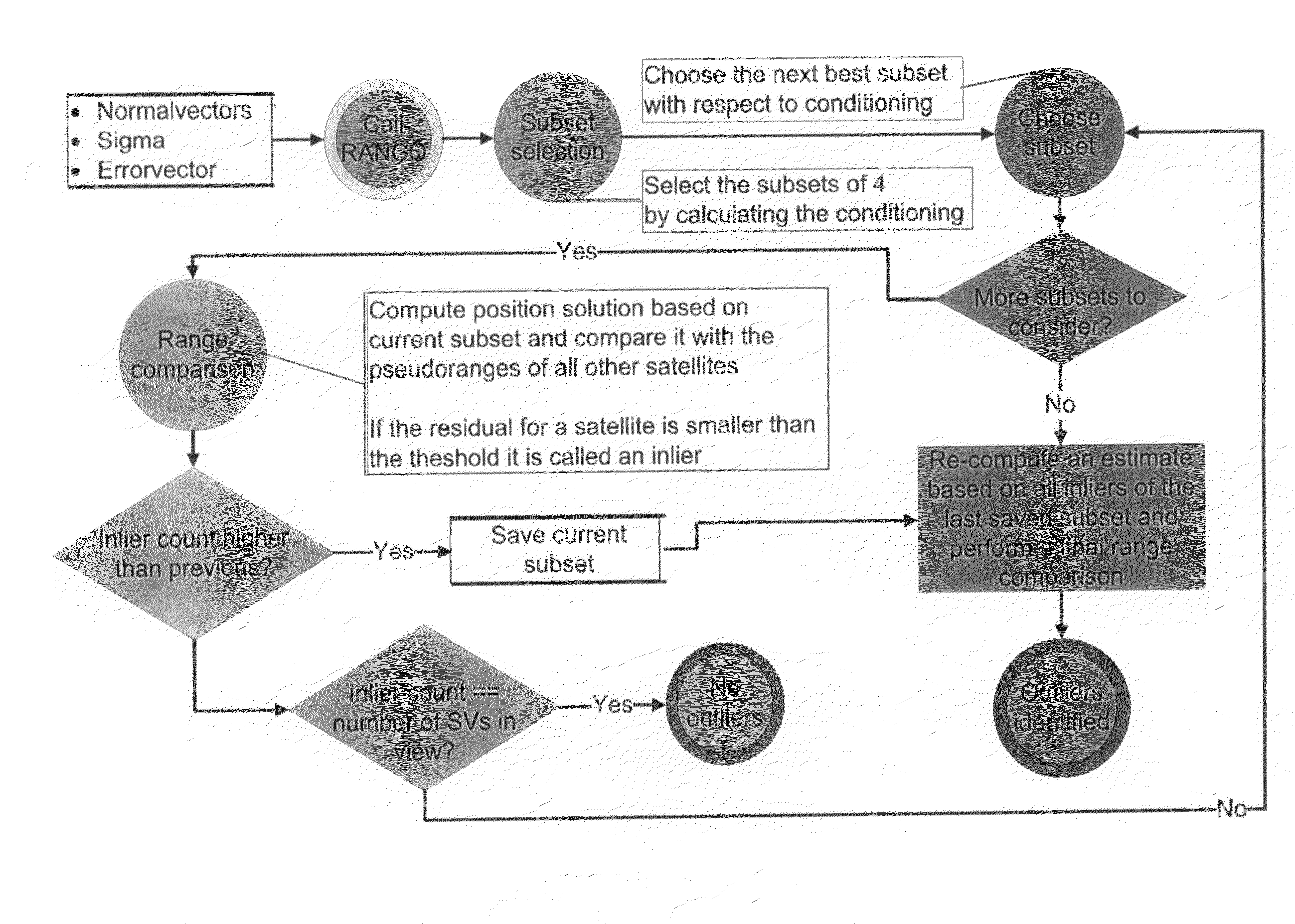
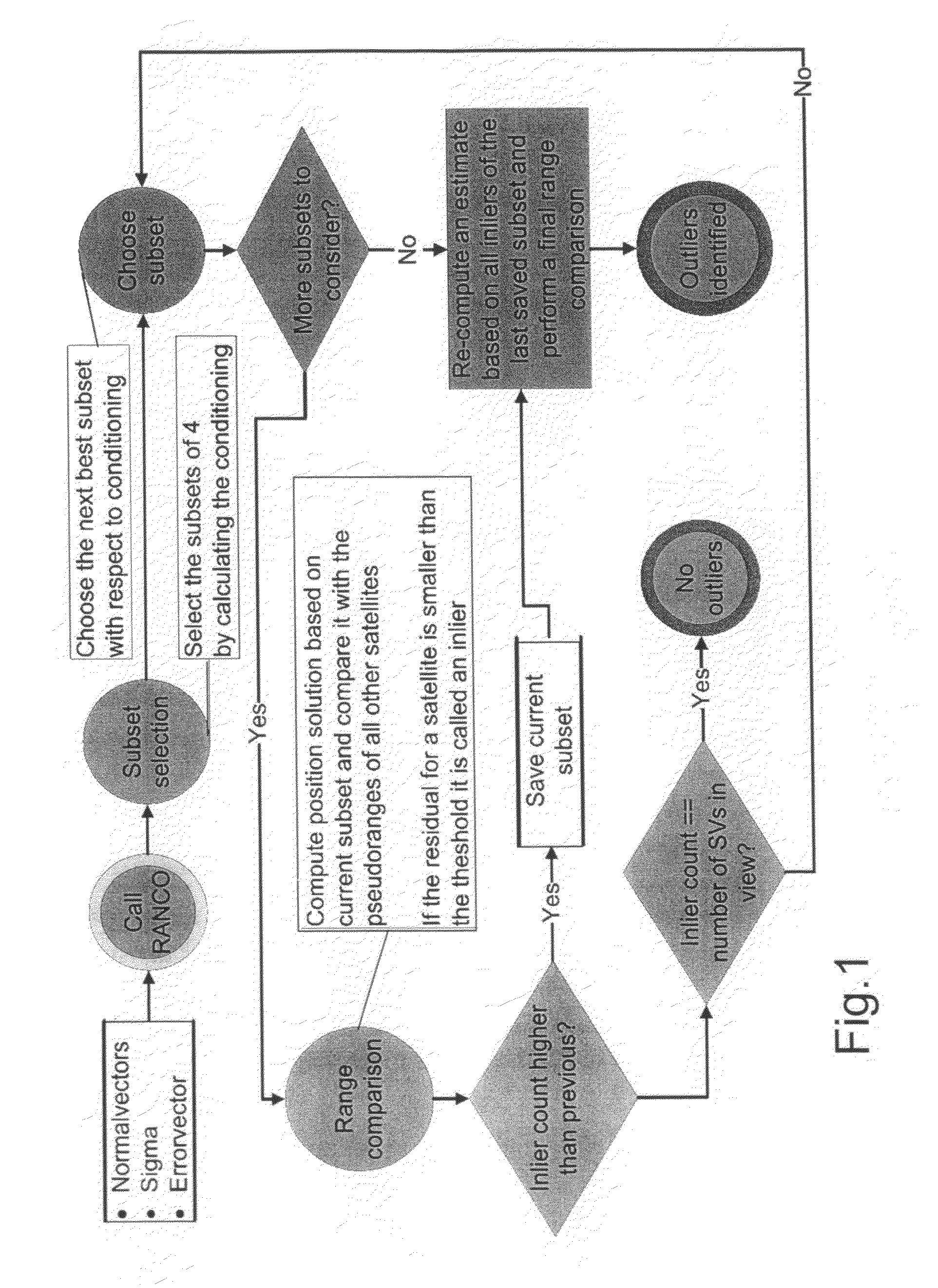
[0049]The new procedure according to the present disclosure, called RANCO, is capable of detecting and identifying all (number of satellites in view minus necessary number of satellites for the position estimation (i.e. four) minus at least one additional satellite) navigation satellite signals with a range bias higher than a given threshold. This paves the way for safety critical and mass-market applications by allowing reliable and accurate estimations of position, velocity, and time at the receiver even during erroneous satellite constellations.

[0050]Further on, by excluding faulty satellite signals at low biases not only the integrity but also the precision of the estimations can significantly be improved. With a good estimate of the current ranging bias of each individual satellite, it is possible to reduce also multipath effects by eliminating the common bias.

[0051]In contrast to known approaches, the new procedure does not compute an estimation of position based on all satell...


PUM


Abstract

A receiver operating with satellite navigation signals estimates its position by means of a multiplicity of signals each transmitted by another satellite. A subset of satellites is used to calculate the position estimation and checking the pseudoranges of all received satellite signals that did not contribute to this particular estimate with respect to their consensus with this estimate. The subset with the best consensus is determined by combining the subsets with respect to the consensus with all ranging sources in view. Consensus in this context refers to pseudoranges that coincide in a position solution in a consistent way. The satellites with a bias in pseudorange higher than a threshold are identified as faulty satellites, after knowing all consistent satellites. This identifying information is then used to exclude the faulty satellites for the determination of position, velocity, and time in the receiver.

Description

BACKGROUND[0001]1. Field of the Disclosure[0002]The present disclosure relates to a method of operating a satellite navigation receiver estimating its position by means of a multiplicity of signals each transmitted by another satellite as ranging source.[0003]2. Discussion of the Background Art[0004]In anticipation of the future Global Navigation Satellite Systems (GNSS) constellations like GPS IIF / III (USA), Galileo (Europe), GLONASS (Russia), and Compass (China) becoming operational, a multitude of questions on the use of these numerous ranging sources will arise. Simulations show that with full Galileo and GPS constellations an average of 18 satellites and a minimum of 13 will be in view for most users. Hence, with the given threat models, the applicability of Receiver Autonomous Integrity Monitoring (RAIM) techniques for the purpose of monitoring position integrity will be increased. Additionally, the use of dual frequency receivers will eliminate almost completely the largest m...

Claims


Application Information

Patent Timeline
IPC IPC(8): G01S1/00G01S19/11
CPCG01S19/20
Inventor SCHROTH, GEORG
Owner DEUTSCHES ZENTRUM FUER LUFT & RAUMFAHRT EV
Why Eureka
Try Eureka