Neck Portion Grinding Apparatus, Grinding Device Employed in the Neck Portion Grinding Apparatus, and Neck Portion Grinding Process

a technology of grinding apparatus and grinding device, which is applied in the direction of abrasive surface conditioning device, programme control, instruments, etc., can solve the problems of low number of stocks, high cost, and difficult to obtain, so as to reduce working man-hours, improve processing accuracy, and work time is shortened

Inactive Publication Date: 2009-11-05
OSG +1
View PDF0 Cites 3 Cited by
  • Summary
  • Abstract
  • Description
  • Claims
  • Application Information

AI Technical Summary

Benefits of technology

[0018]According to a neck portion grinding apparatus as described in Claim 1, since a grinding device including a disc-like grinding wheel and a wheel rotating device for rotating the grinding wheel, and a machine tool including a main shaft for rotatably supporting a rotating tool, and a table mounting the grinding device thereon, the machine tool being adapted to make relative motion of the main shaft and the table by numerical control, are provided, the apparatus has an effect capable of changing a shape of a neck portion of the rotating tool by relatively moving the main shaft and the table while mutually rotating the rotating tool and the grinding wheel, and grinding the rotating tool by the grinding wheel.
[0019]Moreover, since the rotating tool is ground by relatively moving the main shaft (rotating tool) and the table (grinding device), the work time is shortened as compared to the case where the rotating tools are manually ground one by one by the grinder, etc. as in the past, and according to this, an effect capable of reducing working man-hours is given.
[0020]Moreover, since the rotating tool is ground by relatively moving the main shaft (rotating tool) and the table (grinding device), and an effect is given, which can improve processing accuracy with respect to processing of a workpiece by restricting runout of the rotating tool.
[0021]Moreover, since the rotating tool held by the main shaft is ground by the grinding wheel, the rotating tool is ground on the machine tool. Thereby, a rotating shaft at the time of grinding the rotating tool and a rotating shaft at the time of processing the workpiece by using the rotating tool can be made to be the same rotating shaft, so that the effect is given, which can improve the processing accuracy with respect to the processing of the workpiece by restricting the runout of the rotating tool. As a result, processing requirements for processing the workpiece (for example, feed speed and depth of cut) can be improved and an effect capable of improving processing performance of the rotating tool is given.
[0022]Further, if it is possible to grind the rotating tool on the machine tool, a plurality of rotating tools required for processing objects to be machined are previously ground and the rotating tools are prepared for every holders, whereby an effect capable of simplifying the work is given.
[0023]According to a neck portion grinding apparatus as described in Claim 2, in addition to the effect exerted by the neck portion grinding apparatus as described in Claim 1, since the grinding device is adapted to be detachable with respect to the machine tool, a work space can be secured on the table of the machine tool by removing the grinding device. Therefore, the workpiece is fixed while being held in the secured work space by a chuck, etc. and can be processed, so that the machine tool can be used as a cutting-processing machine.

Problems solved by technology

Moreover, as compared with a standard product, a length of whose small diameter section is set to a standard length, there is a slight demand for a special product, a length of whose small diameter section is set to be longer or shorter than that of the small diameter section of the standard product, and the number of stocks thereof is also low, so that the cost thereof is high and it is hard to obtain it.

Method used


Image

  • Neck Portion Grinding Apparatus, Grinding Device Employed in the Neck Portion Grinding Apparatus, and Neck Portion Grinding Process
  • Neck Portion Grinding Apparatus, Grinding Device Employed in the Neck Portion Grinding Apparatus, and Neck Portion Grinding Process
  • Neck Portion Grinding Apparatus, Grinding Device Employed in the Neck Portion Grinding Apparatus, and Neck Portion Grinding Process

Examples


Embodiment Construction

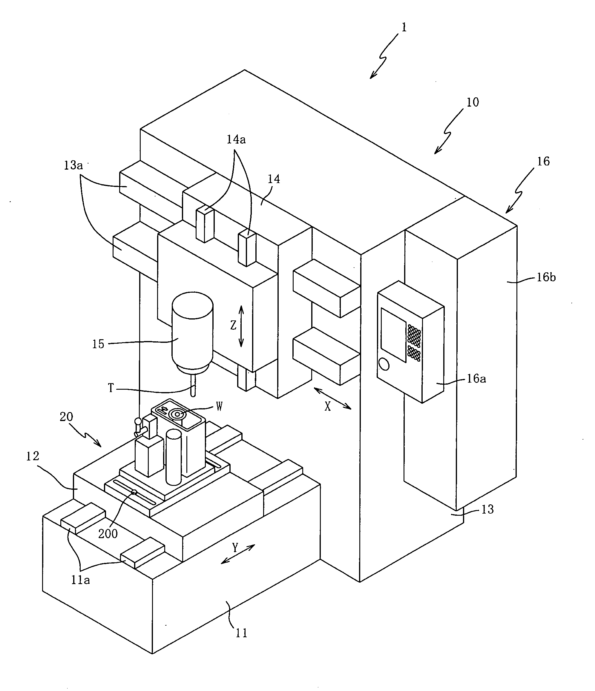
[0049]A preferred embodiment of the present invention will be explained hereinafter with reference to the accompanying drawings. FIG. 1 is a perspective view of a neck portion grinding apparatus 1 according to one embodiment of the present invention.

[0050]First, referring to FIG. 1, a summary of the construction of the neck portion grinding apparatus 1 will be explained. As shown in FIG. 1, the neck portion grinding apparatus 1 mainly includes a machine tool 10 and a grinding device 20, and is an apparatus for changing the shape of the neck portion of a rotating tool T by grinding the rotating tool T by a grinding wheel W of the grinding device 20.

[0051]Concretely, the shape of the neck portion of the rotating tool T is changed by abutting the grinding wheel W on the rotating tool T and grinding the rotating tool T (refer to FIG. 5).

[0052]Next, the detailed constructions of respective sections will be explained. As shown in FIG. 1, the machine tool 10 mainly includes a bed 11 servin...


PUM

PropertyMeasurementUnit
lengthaaaaaaaaaa
radiusaaaaaaaaaa
shapeaaaaaaaaaa

Abstract

A neck portion grinding apparatus and method is designed to reduce working man-hours and to improve processing accuracy with respect to a processing of a workpiece. The neck portion grinding apparatus includes a grinding device having a disc-like grinding wheel and a wheel rotating device for rotating the grinding wheel, and a machine tool having a main shaft for rotatably supporting a rotating tool and a table mounting the grinding device thereon, and relatively moving the main shaft and the table by numeral control. A shape of a neck portion of the rotating tool can be changed by relatively moving the main shaft and the table while mutually rotating the rotating tool and the grinding wheel, and grinding the rotating tool by the grinding wheel.

Description

TECHNICAL FIELD[0001]The present invention relates to neck portion grinding apparatuses, grinding devices employed in the neck portion grinding apparatus, and a neck portion grinding process, in which by grinding a rotating tool, the shape of a neck portion thereof is changed and, particularly, to a neck portion grinding apparatus, a grinding device employed in the neck portion grinding apparatus, and a neck portion grinding method which can reduce working man-hours and improve processing accuracy with respect to a processing of a workpiece.BACKGROUND ART[0002]A neck portion of a rotating tool (a portion between a holder end and a cutting tooth in a case where the rotating tool is mounted to a machine tool) comprises a shank, and a small diameter section formed smaller in diameter than a shank diameter and provided in order to avoid interference with a workpiece (Patent Document 1).[0003]The rotating tool provided with the small diameter section in this way is increased in an amount...

Claims


Application Information

Patent Timeline
Patent Type & Authority Applications(United States)
IPC IPC(8): B24B51/00B24B53/06B24B5/14B24B53/08
CPCB23P23/02B24B5/08G05B2219/45161G05B2219/37611B24B53/053B24B53/06B24B53/08
Inventor AOKI, WATARUTAKAHAMA, HIROTSUGUNAKAMURA, MASAKAZUHAMATAKE, YASUOOSAWA, JIRONAGAI, TAMOTSU
Owner OSG
Why Eureka
Try Eureka