
Method and apparatus for time and frequency transfer in communication networks

a technology of communication network and time and frequency synchronization, applied in multiplex communication, generating/distributing signals, instruments, etc., can solve the problems of inability to accurately correlating information between devices, jitter and wander in packet networks carrying timing-sensitive services, and limited scalability of time division multiplex (tdm) networks,

Inactive Publication Date: 2009-11-05
RPX CLEARINGHOUSE +1
View PDF22 Cites 163 Cited by
  • Summary
  • Abstract
  • Description
  • Claims
  • Application Information

AI Technical Summary

Problems solved by technology

With the increasing need for bandwidth, Time Division Multiplex (TDM) networks face limits in terms of scalability, operational cost and maintenance.
One of the technical challenges holding back the deployment of Carrier Ethernet has been the requirement for very accurate clock synchronization in the network between source and destination, which is an absolutely essential capability for delivering wireless backhaul and leased line services.
Without proper frequency synchronization, packet networks carrying timing-sensitive services can generate excessive jitter and wander when interfacing to TDM devices.
Without synchronized time, accurately correlating information between devices becomes difficult, if not impossible.
In the area of network security, if a network engineer cannot successfully compare logs between each of the routers and all the network servers, it is very hard to develop a reliable picture of an incident.
As a result, carriers rely on expensive solutions such as circuit-based T1 / E1 connections and GPS receivers to ensure accurate synchronization of services across packet networks.
All of these existing timing methods involve considerable capital investment for hardware at a large number of customer sites or base stations.
However, the disadvantage of GPS-based re-timers is that they involve a substantial cost and implementation burden.
There is the need to equip each base station with a GPS receiver, involving a significant capital cost.
Another concern is that the existing GPS may not be an acceptable solution for all sites since GPS signals may be weak indoors or in metropolitan areas.
Moreover, some wireless operators intentionally may not want to use a GPS signal controlled by the United States.
NTP, however, currently does not meet the accuracy requirements for telecom grade time and frequency synchronization.
The problem is that NTP packets go through the Ethernet physical and Media Access Control (MAC) layers in the switches or routers like any other packets, so synchronization is not addressed until the packets reach the end-system software stack.
The main obstacle to the adoption of IEEE 1588 is that the protocol cannot be seamlessly implemented in current / existing native Ethernet interface cards.
The result is the implementation of a protocol that has a cost associated with it that the network engineer may not be willing to incur.
Exact time synchronization over packet networks is difficult to achieve, particularly, when there are uncertainties on transmission delays in the network, and on processing delays in the protocol layers of the end-systems.
Packet Delay Variation (PDV) is a main cause of poor clock synchronization in communication networks.

Method used


Image

  • Method and apparatus for time and frequency transfer in communication networks
  • Method and apparatus for time and frequency transfer in communication networks
  • Method and apparatus for time and frequency transfer in communication networks

Examples


Embodiment Construction

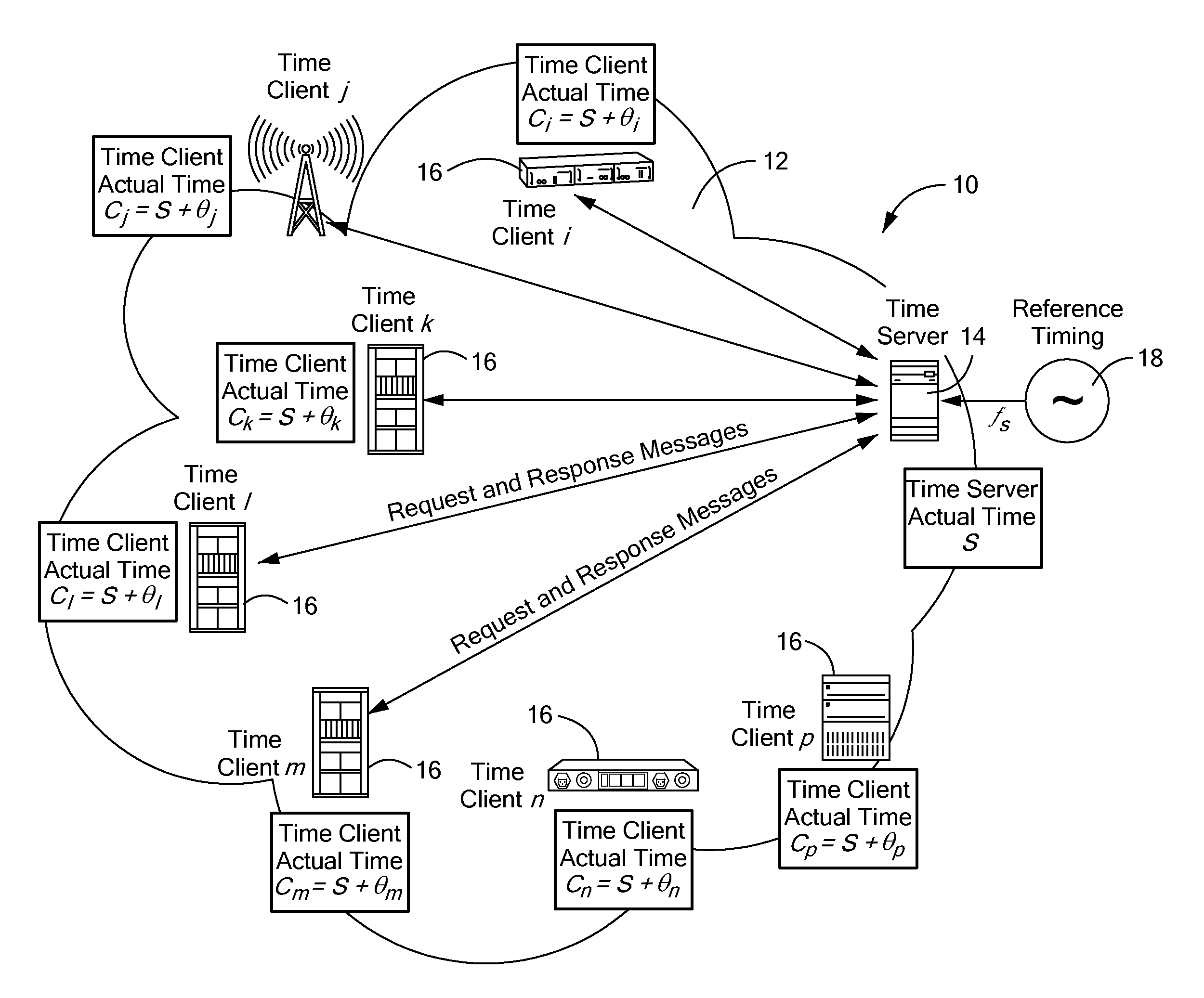
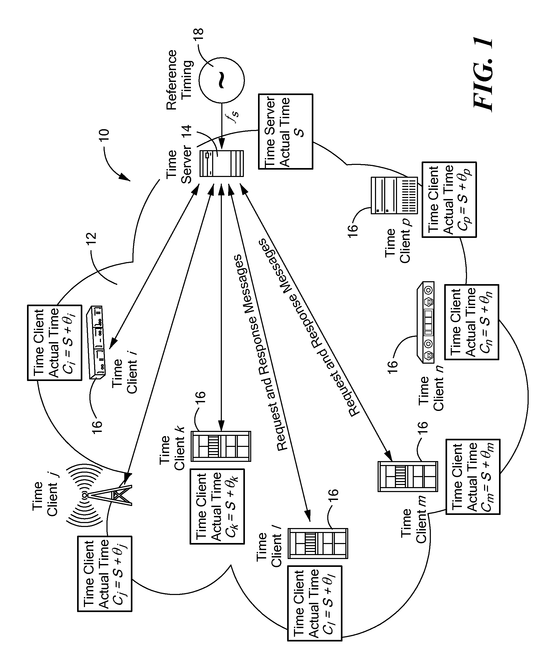
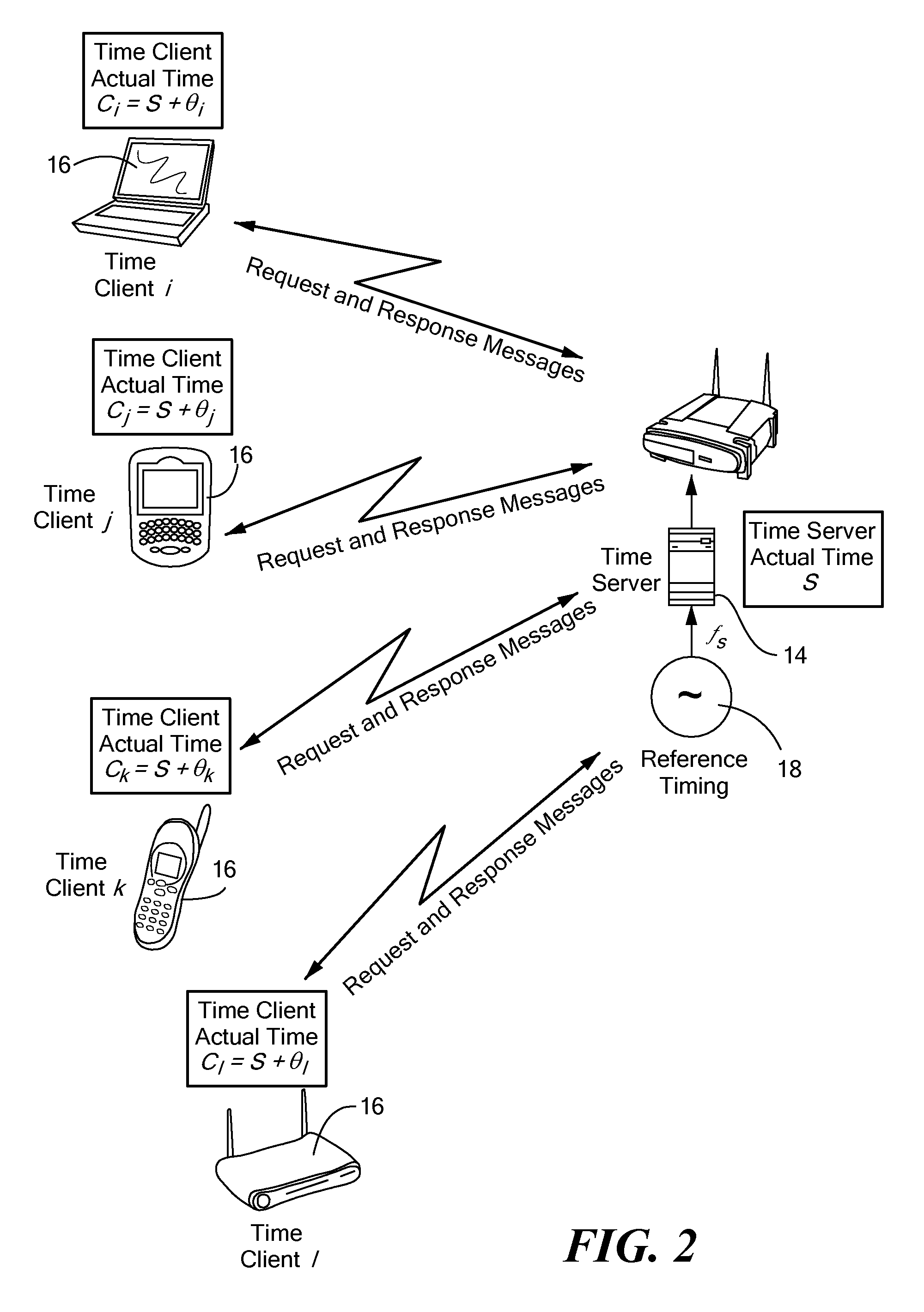
[0030]It is to be understood that both the preceding summary and the following detailed description are exemplary and explanatory and are intended to provide further explanation of the invention as claimed. Neither the summary nor the description that follows is intended to define or limit the scope of the invention to the particular features mentioned in the summary or in the description. The present invention provides a method and system synchronizing timing between a time server and a time client over a packet network.

[0031]The present invention can be implemented in a packet network over which time and frequency are transferred. A central timing system is provided which consists of a time server and timing transfer node (e.g., router, switch, gateway, wireless access point, etc.), and time clients (e.g., router, switch, gateway, wireless access point, desktop computer, laptop, personal digital assistant (PDA), VoIP phone, data server, etc.). The communication between a timer ser...


PUM


Abstract

A timing system for time synchronization between a time server and a time client over a packet network. The timing system includes a time server for generating current timestamp information and a time client having a phase-locked loop driven client clock counter. The time client periodically exchanges time transfer protocol messages with the time server over the packet network, and calculates an estimated client time based on the timestamp information. The phase-locked loop in the time client receives periodic signals representing the estimated server time as its input and calculates a signal which represents the error difference between the estimated server time and the time indicated by the time client clock counter. The error difference eventually converges to zero or a given error range indicating the time presented by the client clock counter, which is driven by the phase-locked loop having locked onto the time of the time server.

Description

CROSS-REFERENCE TO RELATED APPLICATION[0001]n / aSTATEMENT REGARDING FEDERALLY SPONSORED RESEARCH OR DEVELOPMENT[0002]n / aFIELD OF THE INVENTION[0003]The present invention relates to time and frequency synchronization in packet networks and more specifically to a method and system that incorporates a time transfer protocol and phase-locked loop (PLL) architecture to address the problem of packet delay variation (PDV) in packet networks.BACKGROUND OF THE INVENTION[0004]With the increasing need for bandwidth, Time Division Multiplex (TDM) networks face limits in terms of scalability, operational cost and maintenance. This results in telecommunications carriers having to replace circuit-based transport with packet-based (Ethernet) transport to realize cost and operational efficiencies, meet increasing bandwidth demands from customers at reasonable price points, bring a new level of flexibility and dynamic configuration to the network, and offer more tiered and time-based or on-demand serv...

Claims


Application Information

Patent Timeline
Patent Type & Authority Applications(United States)
IPC IPC(8): G06F15/16
CPCH04J3/0667H04L67/02H03L7/18H03L7/093H03L7/08
Inventor AWEYA, JAMESBARBOSA, LUIS OROZCO
Owner RPX CLEARINGHOUSE
Learn More