Supporting strut for supporting an intermediate deck that is arranged in an aircraft fuselage, and method for producing a rod body for such a supporting strut

Active Publication Date: 2009-11-12
AIRBUS HELICOPTERS DEUT GMBH
View PDF11 Cites 4 Cited by
  • Summary
  • Abstract
  • Description
  • Claims
  • Application Information

AI Technical Summary

Benefits of technology

[0005]It is the object of the present invention to create a supporting strut whose rod body features a lightweight construction while at the same time providing good buckling resistance and resistance to damage, as well as providing improved fire-resistance characteristics.
[0009]The prepreg interlaid scrim that arises by stack formation with the at least one first reinforcement layer together with the at least one second reinforcement layer can be designed such that a first reinforcement layer is arranged immediately adjacent to a second reinforcement layer, or such that several first reinforcement layers are combined with several second reinforcement layers and any others. The prepreg interlaid scrim used according to the invention features a fine count structure and in its final state is comparatively more resistant to impact loads. With the use of a special production method, which is explained below, good strength can be achieved with relatively thin walls. This method is based on repeated thermal compacting that reduces the settling distance of the material, reduces the risk of folds developing when the material is wound onto the mandrel, reduces the incidence of cavity formation and also stabilises the selected fibre orientation.
[0013]Preferably, in this way two to four prepreg interlaid scrims are formed by repeatedly carrying out the steps set out above so as to ensure adequate wall thickness while at the same time maintaining light weight. Each time, the woven textile tape that is used for second intermediate compacting is preferably removed, by unwinding, prior to the mandrel next being wrapped with a further prepreg interlaid scrim so that the thinnest-possible wall thicknesses can be achieved. The woven textile tape does not contribute to the stability of the rod body but instead is only used in a corset-like manner during production in order to generate an external counterforce when the material on the mandrel on the inside expands as a result of an increase in the temperature, thus causing the desired compacting effect. At the same time, as a result of this, air is evacuated from the fibre reinforced material, and excess artificial resin is removed. It is important to understand that compacting does not result in complete solidification of the artificial resin. Instead, complete curing of the artificial resin is achieved during a final processing step that will be described below. After all the reinforcement layers have been applied, and after intermediate compacting of them has been completed, a glass fibre prepreg is applied as a final single layer.
[0016]This ensures that excess artificial resin is reliably removed to maximise stability, and that overall an outer surface of corresponding quality results. This is a prerequisite for any damage that the rod body may sustain becoming more easily visible.

Problems solved by technology

Such rod bodies are associated with a disadvantage as a result of the deviation of the fibre alignment from the optimal alignment, which deviation is due to the production process, thus resulting in thicker wall thicknesses in the dimensioning that is required to achieve adequate buckling resistance.
Associated with this, the rod body has a comparatively heavier weight, which is basically undesirable in aircraft construction.
Rod bodies produced in this way are associated with a further disadvantage in that shock loading can have a significant negative effect on the stability of the supporting strut.
Known supporting struts are thus comparatively susceptible to damage.
Furthermore, due to the material used, meeting the required fire-resistance characteristics is problematic or often achievable only with the use of additional measures, for example special coatings.

Method used


Image

  • Supporting strut for supporting an intermediate deck that is arranged in an aircraft fuselage, and method for producing a rod body for such a supporting strut
  • Supporting strut for supporting an intermediate deck that is arranged in an aircraft fuselage, and method for producing a rod body for such a supporting strut
  • Supporting strut for supporting an intermediate deck that is arranged in an aircraft fuselage, and method for producing a rod body for such a supporting strut

Examples


Embodiment Construction

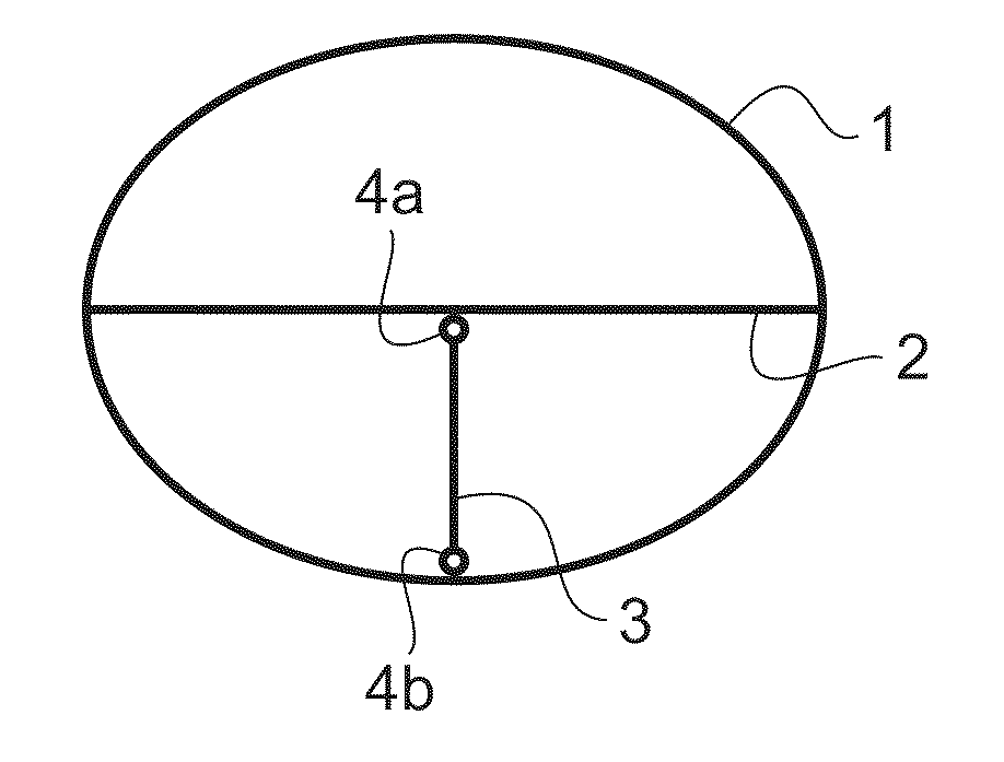
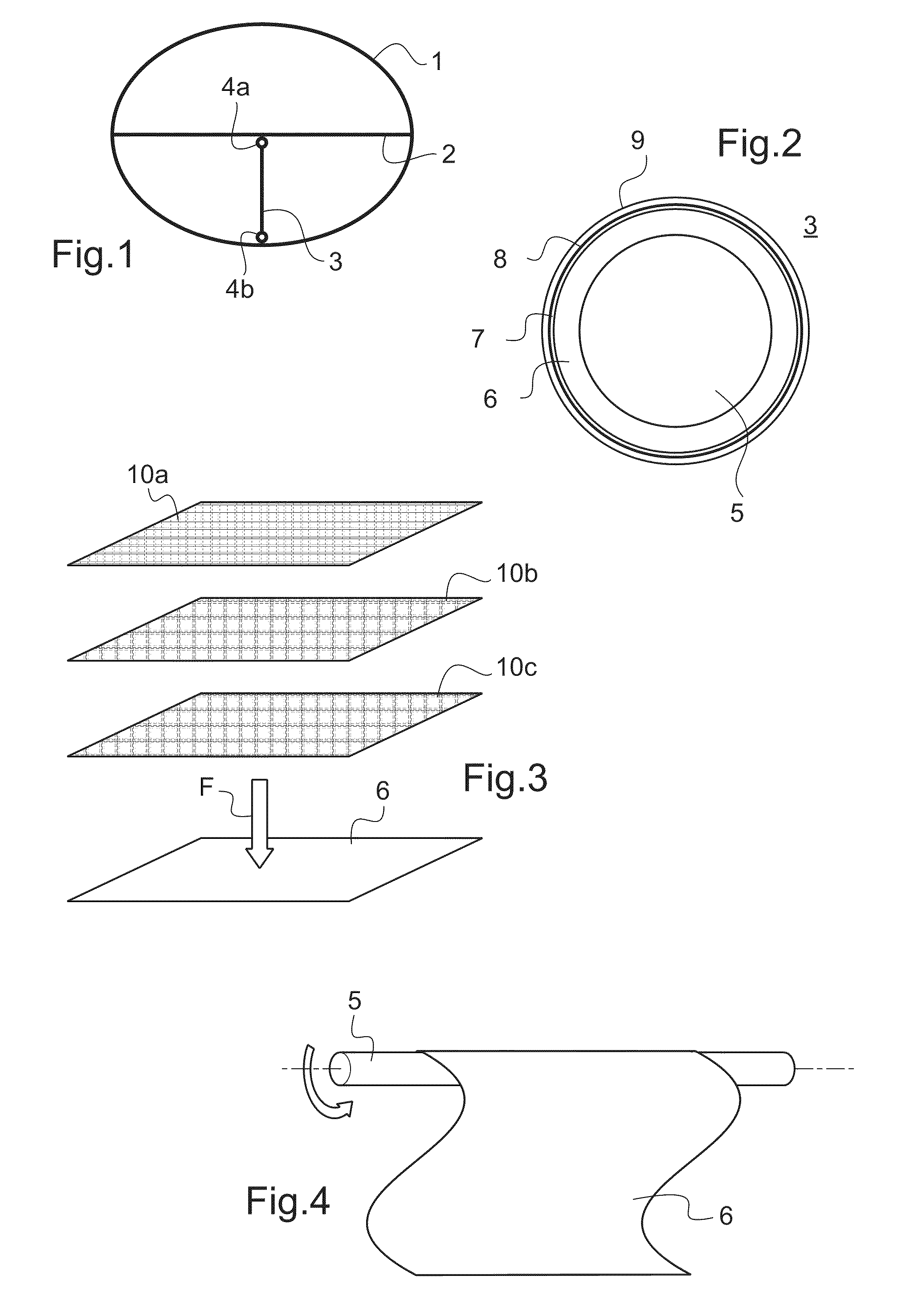
[0029]According to FIG. 1, within an aircraft fuselage 1 there is an intermediate deck 2 that approximately in the centre is supported by a supporting strut that comprises a rod body 3, which supporting strut extends between the intermediate deck 2 and the aircraft fuselage 1 and on each of its ends comprises a rod end 4a, 4b for detachable attachment. The two rod ends 4a and 4b are made from light metal and are inserted in the hollow cylindrical rod body 3. Affixation in the installed position takes place by means of an adhesive.

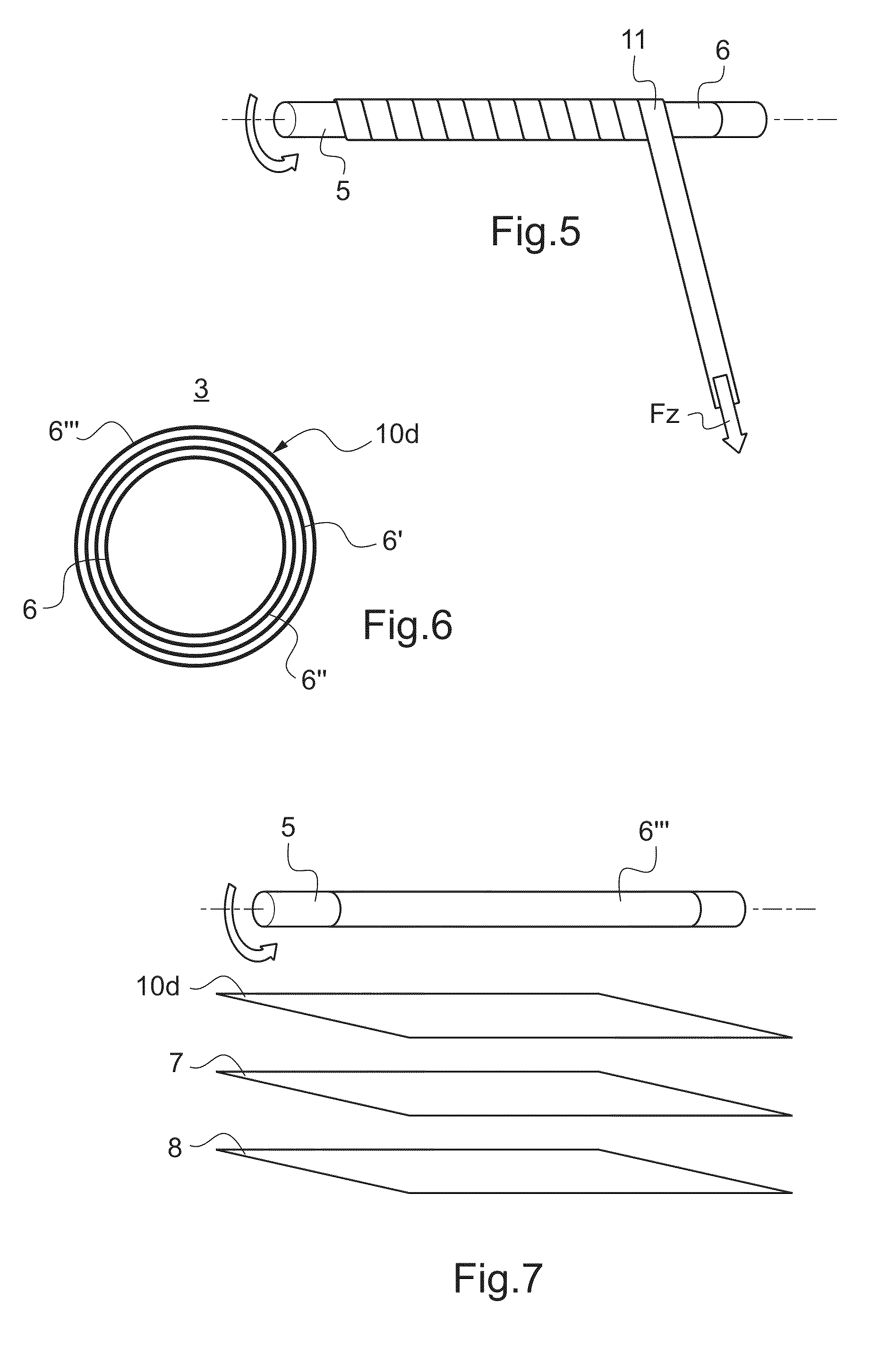
[0030]According to FIG. 2 the rod body 3 of the supporting strut comprises a multilayer design; in the exemplary embodiment shown it comprises prepreg interlaid scrim 6, wrapped around an aluminium mandrel 5, the design of which prepreg interlaid scrim 6 will be explained in more detail below. In the illustration, for the purpose of clarifying final curing, a peel ply layer 7 is applied around the prepreg interlaid scrim 6 that comprises several reinforceme...


PUM

PropertyMeasurementUnit
Timeaaaaaaaaaa
Timeaaaaaaaaaa
Angleaaaaaaaaaa

Abstract

A supporting strut for supporting an intermediate deck (2) that is arranged in an aircraft fuselage (1), includes a hollow cylindrical rod body (3) that includes a fibre reinforced material, with the two ends of the rod body (3) being designed as attachment sections for detachable attachment to the aircraft fuselage (1) or to the intermediate deck (2), wherein the rod body (3) includes at least one first reinforcement layer (10a) made from a carbon fibre fabric with an identical number of warp- and weft threads in 45° alignment or 90° alignment, as well as at least one second reinforcement layer (10b, 10c) made from a carbon fibre fabric including a higher number of warp threads than weft threads in 0° alignment, as well as a final layer including glass fibre, which together with artificial resin form a compact fibre reinforced material.

Description

[0001]The present invention relates to a supporting strut for supporting an intermediate deck that is arranged in an aircraft fuselage, with said supporting strut comprising a hollow cylindrical rod body that comprises a fibre reinforced material, wherein the two ends of said rod body are designed as attachment sections for detachable attachment to the aircraft fuselage or to the intermediate deck. Apart from this, the invention also comprises a method for producing such a rod body. Furthermore, an aircraft comprising a fuselage in which such supporting struts are installed forms part of the invention.BACKGROUND OF THE INVENTION[0002]Aircraft of the type of interest in the present document comprise at least one intermediate deck that extends across an aircraft fuselage in order to create a multi-level design. In a commercial aircraft such an intermediate deck is, for example, provided in order to install passenger seats thereon, which passenger seats occupy the upper region of the a...

Claims


Application Information

Patent Timeline
IPC IPC(8): B64C1/06B29C53/60
CPCB29C53/582Y10T428/24058B29C70/222B29C70/32B29C70/34B29C2053/8025B29K2707/04B29K2709/08B29L2023/00B29L2031/3082B64C1/18Y02T50/433Y10T428/24074Y10T428/24099B29C53/60B32B1/08B32B3/266B32B5/024B32B5/26B32B7/06B32B7/12B32B2260/021B32B2260/046B32B2262/101B32B2262/106B32B2307/3065B32B2307/714B32B2605/18B32B7/03Y02T50/40
Inventor BERGMANN, ANTONSEDLMEIER, MARINUS
Owner AIRBUS HELICOPTERS DEUT GMBH
Why Eureka
Try Eureka