
Plasma reactor

a reactor and plasma technology, applied in the field of plasma reactors, can solve the problems of non-uniformity of etching rate in etching process, inability to enable uniform effective discharge of exhaust gas along the periphery,

Active Publication Date: 2009-11-12
DMS CO LTD
View PDF1 Cites 9 Cited by
  • Summary
  • Abstract
  • Description
  • Claims
  • Application Information

AI Technical Summary

Benefits of technology

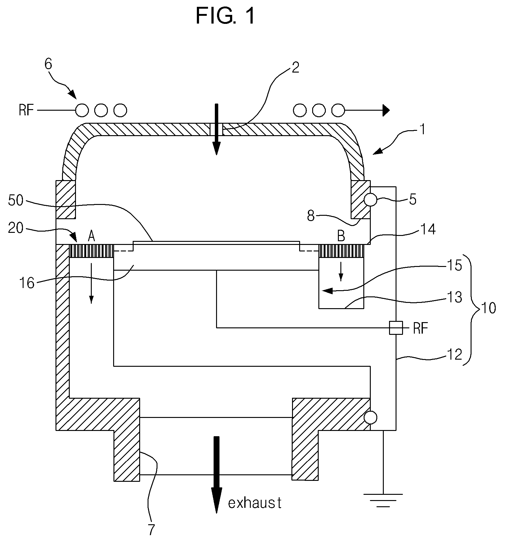
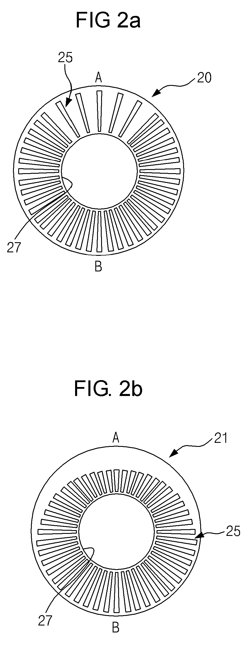
[0011]An aspect of exemplary embodiments of the present invention is to address at least the problems and / or disadvantages and to provide at least the advantages described below. Accordingly, an aspect of exemplary embodiments of the present invention is to enable uniform effective discharge of reaction gas along the periphery of a substrate support within a chamber by installing a baffle plate for discharging reaction gas along the periphery of the substrate support and asymmetrically arranging and forming vents in the baffle plate such that the reaction gas can be discharged uniformly.
[0012]Another aspect of exemplary embodiments of the present invention is to, by keeping plasma on a substrate surface uniform, keep the uniformity of an etching rate on the whole substrate surface in an etching process, etc. and improve process uniformity.

Problems solved by technology

The first problem is that, when reaction gas generated after plasma reaction, polymer, or particles are discharged below the chamber, it is obstructed by the cathode support shaft supporting the cathode assembly, thus disabling uniform effective discharge of exhaust gas along the periphery of the cathode assembly.
The second problem is that, when reaction gas is discharged, it is obstructed by the cathode support shaft at one side and, because the reaction gas is non-uniformly discharged, plasma cannot be uniformly formed on a substrate surface, thus causing the non-uniformity of an etching rate in an etching process, etc.

Method used


Image

  • Plasma reactor
  • Plasma reactor
  • Plasma reactor

Examples


Embodiment Construction

[0035]Exemplary embodiments of the present invention will now be described in detail with reference to the annexed drawings. In the following description, a detailed description of known functions and configurations incorporated herein has been omitted for conciseness.

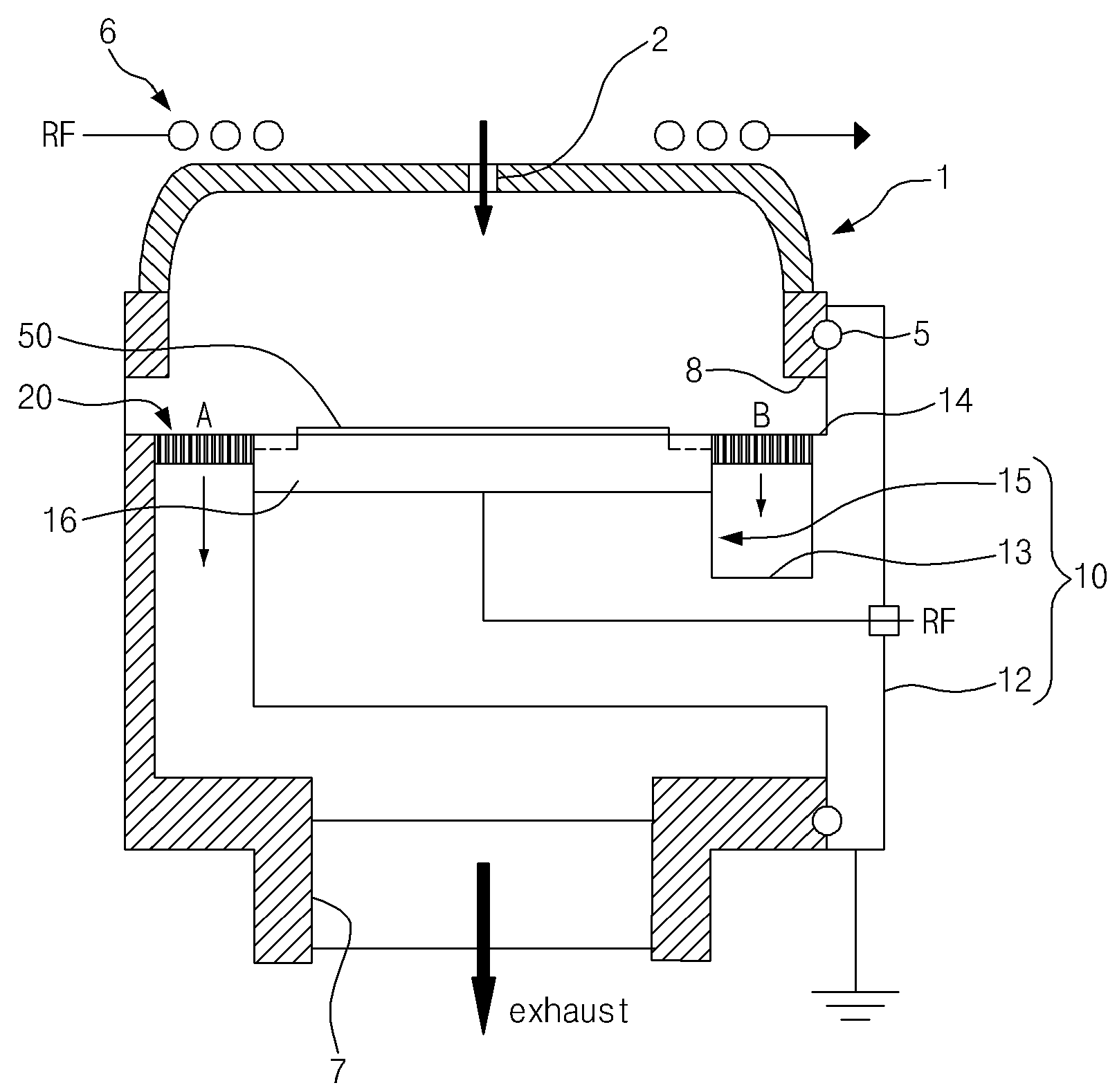
[0036]FIG. 1 is a schematic side section of an exemplary embodiment of the present invention. FIGS. 2A to 2C are plan views of respective different exemplary embodiments of a baffle plate.

[0037]As shown, an exemplary embodiment of the present invention includes a chamber 1 for providing a plasma reaction space, and a cathode assembly 10 and a baffle plate 20 installed within the chamber 1.

[0038]The chamber 1 forms the plasma reaction space therein. At a top and center of the chamber 1, a jet port 2 for jetting a reaction gas is formed. At a bottom and center of the chamber 1, an exhaust port 7 for exhausting the reaction gas to the external is formed.

[0039]A Radio Frequency (RF) top electrode 6 is provided over the cha...


PUM

PropertyMeasurementUnit
Lengthaaaaaaaaaa
Areaaaaaaaaaaa
Distanceaaaaaaaaaa

Abstract

A plasma chemical reactor is provided. The reactor includes a chamber, a cathode assembly, and a baffle plate. The chamber forms a plasma reaction space. The cathode assembly includes a cathode support shaft and a substrate support. The cathode support shaft is coupled at one side to a wall surface of the chamber. The substrate support is coupled to the other side of the cathode support shaft and supports the substrate. The baffle plate is out inserted and coupled to the substrate support, and has a plurality of vents arranged to be spaced apart and through formed such that reaction gas can pass through, and the vents asymmetrically arranged and formed to get a vent area smaller at an opposite side than a top side of the cathode support shaft.

Description

CROSS REFERENCE[0001]This application claims foreign priority under Paris Convention and 35U.S.C. § 119 to each of Korean Patent Application No. 10-2008-0043422 filed on May 9, 2008 with the Korean Intellectual Property Office.BACKGROUND OF THE INVENTION[0002]1. Field of the Invention[0003]The present invention relates to a plasma reactor for processing a large-sized wafer. More particularly, the present invention relates to a plasma reactor constructed to have a chamber, a cathode assembly supported on a one side wall surface of the chamber in a cantilever form and supporting a substrate, and a baffle plate for discharging reaction gas. The baffle plate enables asymmetric arrangement of vents for discharging reaction gas and enables uniform discharge of exhaust gas even in the cathode assembly of an asymmetric structure, thereby improving the uniformity of plasma within the chamber and improving the uniformity of a substrate etching rate in an etching process, etc.[0004]2. Descript...

Claims


Application Information

Patent Timeline
IPC IPC(8): B01J19/08H01L21/306
CPCH01J37/32633H01J37/32623H01J37/3244H01J37/32532H01J2237/334
Inventor PARK, KUNJOOCHAE, HWANKOOKKO, SUNGYONGKIM, KEEHYUNLEE, WEONMOOK
Owner DMS CO LTD
Learn More