Porous substrate holder with thinned portions

a substrate holder and porous technology, applied in the direction of coatings, metallic material coating processes, chemical vapor deposition coatings, etc., can solve the problems of non-zone use in the manufacturing of integrated circuits, backside deposition, and non-uniform thickness of substrates

Inactive Publication Date: 2009-11-12
ASM AMERICA INC
View PDF18 Cites 278 Cited by
  • Summary
  • Abstract
  • Description
  • Claims
  • Application Information

AI Technical Summary

Problems solved by technology

The exclusion zone is not used in the manufacturing of integrated circuits for commercial use, due to the non-uniformity of deposition there.
One problem associated with CVD is the phenomenon of “backside deposition.” Many substrate holders are unsealed at the substrate perimeter so that process gases can flow down around the peripheral edge of the substrate and into the gap between the substrate and the substrate holder.
This undesirable deposition creates non-uniformities in substrate thickness, generally detected by local site flatness tools.
Such non-uniformities in substrate thickness can adversely affect chucking down of the substrate, and thus make impossible subsequent processing steps, such as photolithography.
However, the unsealed substrate perimeter permits limited cleaning gas to contact the backside of the substrate, thus resulting in oxide removal on the substrate backside.
The amount of cleaning gas that contacts the substrate backside is ordinarily not sufficient to remove the entire oxide layer from the backside in a typical timeframe for native oxide removal from the substrate front side.
However, at some locations, the cleaning gas tends to create pinhole openings in the oxide layer on the substrate backside, exposing the silicon surface.
Conventional substrate holder syste...

Method used


Image

  • Porous substrate holder with thinned portions
  • Porous substrate holder with thinned portions
  • Porous substrate holder with thinned portions

Examples


Embodiment Construction

[0036]The following detailed description of the preferred embodiments and methods presents a description of certain specific embodiments to assist in understanding the claims. However, one may practice the present invention in a multitude of different embodiments and methods as defined and covered by the claims.

[0037]Referring more specifically to the drawings for illustrative purposes, the present invention is embodied in the devices generally shown in the Figures. It will be appreciated that the apparatuses may vary as to configuration and as to details of the parts, and that the methods may vary as to the specific steps and sequence, without departing from the basic concepts as disclosed herein.

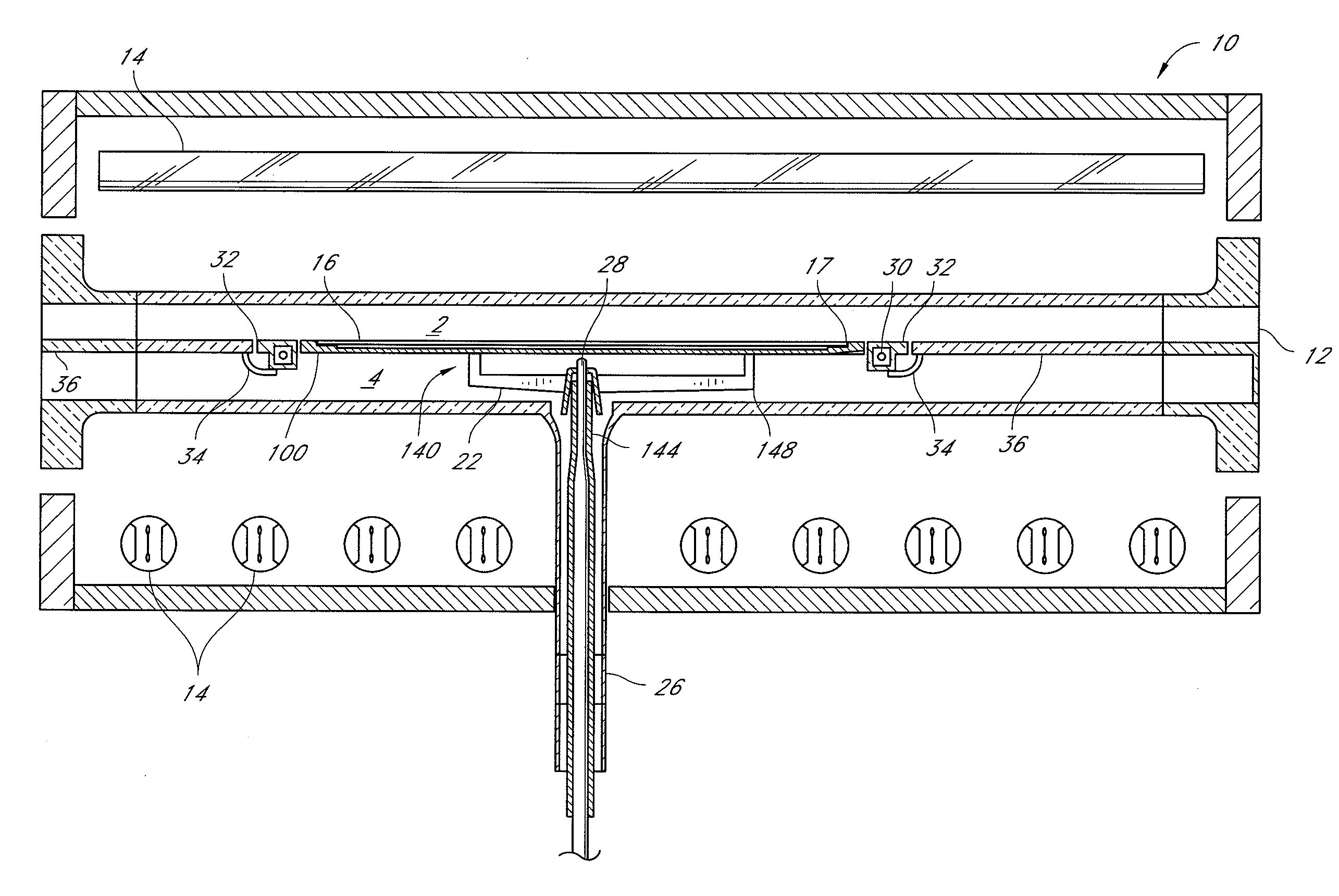
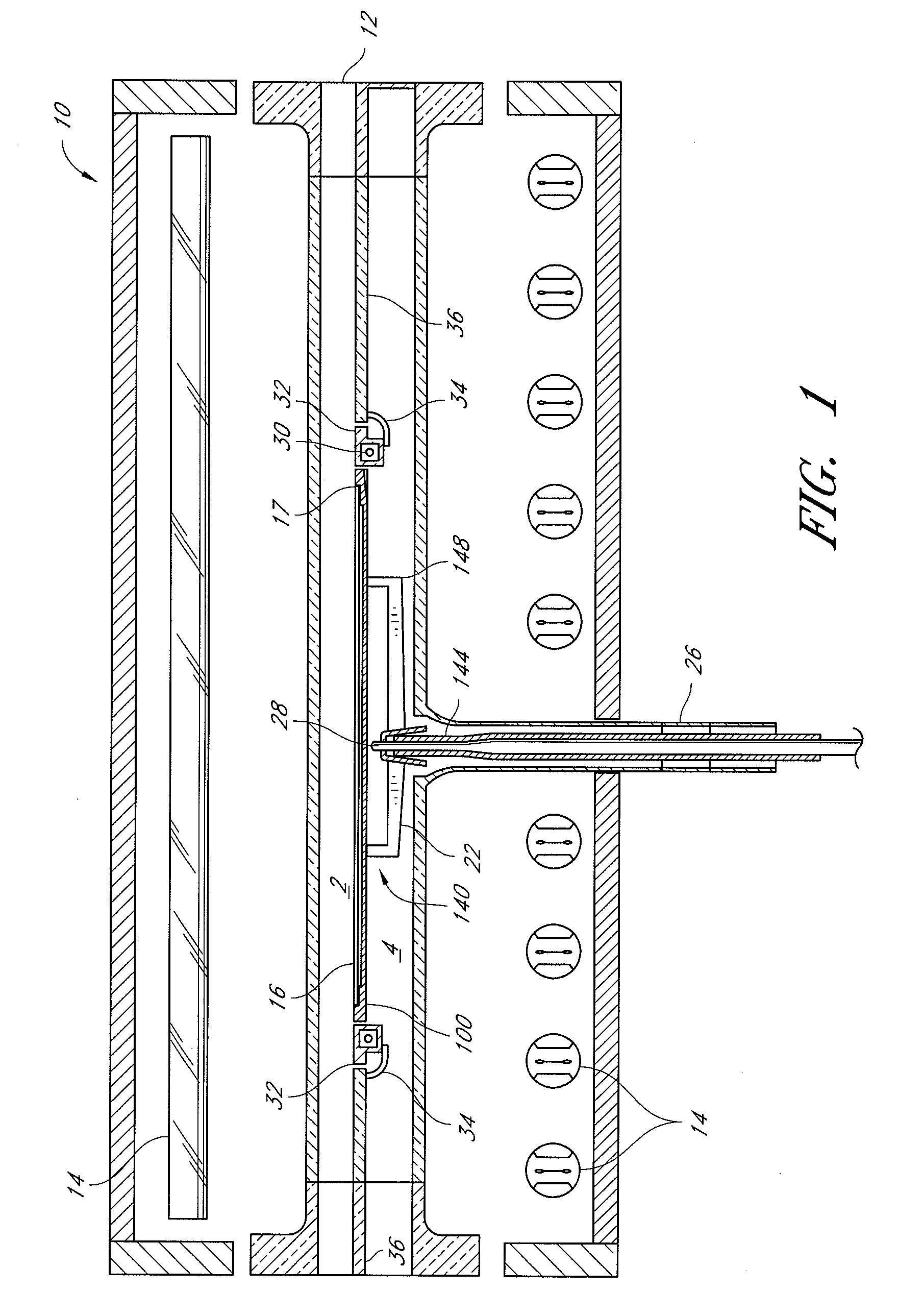
[0038]Prior to describing certain embodiments of the substrate holder, an exemplary CVD reactor is disclosed. FIG. 1 illustrates an exemplary CVD reactor 10, including a quartz reaction chamber 12. Radiant heating elements 14 are supported outside the transparent chamber 12 to provide heat...


PUM

PropertyMeasurementUnit
Fractionaaaaaaaaaa
Thicknessaaaaaaaaaa
Densityaaaaaaaaaa

Abstract

A substrate support system comprises a substrate holder for supporting a substrate. The substrate holder comprises a central portion sized and shaped to extend beneath most or all of a substrate supported on the substrate holder. The central portion has one or more recesses defining thinned portions of the central portion. The one or more thinned portions may comprise at least about 10% of an upper or lower surface of the central portion. The central portion is formed of a porous material, such as a material having a porosity between about 10-40%, configured to allow gas flow therethrough.

Description

BACKGROUND[0001]1. Field of the Invention[0002]The present invention relates to semiconductor substrate handling systems and, in particular, relates to systems and methods for supporting a substrate during material deposition processes.[0003]2. Description of the Related Art[0004]High-temperature ovens, or reactors, are used to process substrates for a variety of reasons. In the electronics industry, substrates, such as semiconductor wafers, are processed to form integrated circuits. In a reaction process, a substrate, typically a circular silicon wafer, is placed on a substrate holder. In some processes, the substrate holder helps to attract radiation and more evenly heat the substrate. These substrate holders are sometimes referred to as susceptors. The substrate and substrate holder are enclosed in a reaction chamber, typically made of quartz, and heated to high temperatures by a plurality of radiant heat lamps placed around the quartz chamber.[0005]In an exemplary high temperatu...

Claims


Application Information

Patent Timeline
IPC IPC(8): C23C16/44
CPCC23C16/4581H01L21/68735H01L21/68792H01L21/68785H01L21/68757
Inventor GOODMAN, MATTHEW G.VYNE, ROBERT M.
Owner ASM AMERICA INC
Why Eureka
Try Eureka